

Non-Inverting Amplifier using Op-Amp
Adapted from the ExpEYES blog lab on the non-inverting op-amp. For the inverting companion experiment, see Inverting Amplifier using Op-Amp.
1. Aim
To build a non-inverting op-amp amplifier using OP07, verify its voltage gain (same phase as the input), and study output clipping when the required output exceeds the supply rails.
2. Apparatus / Components Required
- SEELab3 / ExpEYES-17 unit
- OP07 (or similar) op-amp
- Ground resistor: $R_i = 1\text{ k}\Omega$
- Feedback resistor: $R_f = 10\text{ k}\Omega$
- Dual supply for the op-amp: approximately $\pm 6\text{ V}$
- Breadboard and connecting wires
- PC/mobile with SEELab3 software
3. Theory & Principle
In the non-inverting configuration the signal is applied to the non-inverting (+) input. Feedback from the output to the inverting (−) input forms a voltage divider with $R_f$ and $R_i$ (to ground).
Ideal closed-loop gain:
\[A_v = \frac{V_{out}}{V_{in}} = 1 + \frac{R_f}{R_i}\]With $R_i = 1\text{ k}\Omega$ and $R_f = 10\text{ k}\Omega$:
\[A_v = 1 + 10 = 11\]So the output should be:
- about 11 times the input amplitude (while linear),
- in phase with the input (not inverted).
If $V_{in}$ is too large, $A_v\cdot V_{in}$ exceeds the supply swing and the output clips.
4. Circuit Diagram / Setup
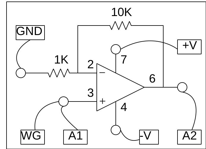
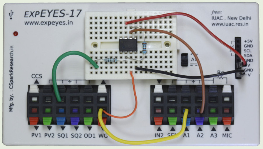
- Power the OP07 with dual rails (about $+6\text{ V}$ and $-6\text{ V}$).
- Apply the WG sine to the non-inverting (+) input.
- Connect $R_i = 1\text{ k}\Omega$ from the inverting (−) input to GND.
- Connect $R_f = 10\text{ k}\Omega$ from the op-amp output back to the inverting (−) input.
- Measure input on A1 (WG / input node) and output on A2 (op-amp output).
- Start with WG amplitude about 80 mV (try ~1 V later to see clipping).
5. Procedure
- Wire the circuit and check supply polarity before applying WG.
- Set WG to a sine (e.g. 200 Hz–1 kHz) at about 80 mV.
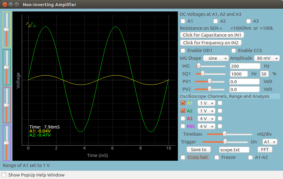
- Observe A1 (input) and A2 (output) on the oscilloscope.
- Record $V_{in,pp}$, $V_{out,pp}$, and confirm they are in phase.
- Compute $A_v = V_{out,pp}/V_{in,pp}$ and compare with 11.
- Increase amplitude toward ~1 V and note the onset of clipping.
Optional — Python capture
1
2
3
4
5
6
7
8
9
10
11
12
13
14
15
16
import eyes17.eyes
from pylab import *

p = eyes17.eyes.open()
p.set_sine(200)

t, v, tt, vv = p.capture2(500, 20)  # A1 and A2

xlabel("Time (ms)")
ylabel("Voltage (V)")
plot([0, 10], [0, 0], "black")
ylim([-4, 4])
plot(t, v, linewidth=2, color="blue", label="A1 input")
plot(tt, vv, linewidth=2, color="red", label="A2 output")
legend()
show()
6. Observation Table
| Trial | $V_{in,pp}$ (V) | $V_{out,pp}$ (V) | Calculated $A_v$ | Phase (same / inverted) | Waveform quality |
|---|---|---|---|---|---|
| 1 (small signal) | |||||
| 2 | |||||
| 3 (near clipping) |
7. Results and Discussion
- Measured gain in the linear region was approximately ____ (theory $A_v = 11$).
- Input and output were in phase.
- At higher amplitude, output clipped near the supply limits.
- Compared with the inverting amplifier ($A_v = -R_f/R_i$), this circuit has positive gain and no phase inversion.
8. Precautions
- Confirm OP07 pinout before wiring.
- Use correct dual-supply polarity.
- Start near 80 mV input; increase gradually.
- Keep SEELab and amplifier grounds common.
- Do not confuse with the inverting topology (input must go to +, not through $R_i$ into −).
9. Troubleshooting
| Symptom | Possible Cause | Corrective Action |
|---|---|---|
| No output | Missing rails / wrong pins | Check power and output pin |
| Gain ≈ −10 or inverted | Built the inverting circuit by mistake | Move signal to +; $R_i$ to GND from − |
| Gain not near 11 | Wrong $R_f$/$R_i$ | Recheck 10 kΩ / 1 kΩ |
| Clipping at low input | Rails too low or wiring error | Verify $\pm 6\text{ V}$ and feedback |
10. Viva-Voce Questions
Q1. Why is this called a non-inverting amplifier?
Ans: The output is in phase with the input; a positive input excursion produces a positive output excursion.
Q2. Derive $A_v = 1 + R_f/R_i$.
Ans: With ideal feedback, $V_+ = V_- = V_{in}$. The divider on the feedback path gives $V_- = V_{out}\cdot R_i/(R_i+R_f)$. Setting $V_- = V_{in}$ yields $V_{out}/V_{in} = 1 + R_f/R_i$.
Q3. What happens if $R_f < R_i$?
Ans: Gain is still $1 + R_f/R_i$, so it remains greater than 1 but closer to unity (e.g. $R_f = R_i$ gives $A_v = 2$).
Q4. How does this differ from the inverting amplifier?
Ans: Inverting: signal into − via $R_i$, + grounded, $A_v = -R_f/R_i$. Non-inverting: signal into +, feedback divider on −, $A_v = 1 + R_f/R_i$, same phase.