
Measuring Pendulum Time Period
1. Aim
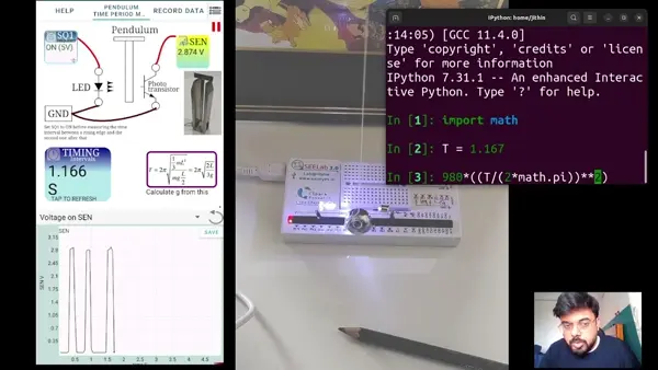
To measure a pendulum’s time period using an optical light barrier (LED + phototransistor) and a timing function on SEELab3/ExpEYES.
2. Apparatus / Components Required
- SEELab3 / ExpEYES-17 unit
- LED (light source)
- Phototransistor (detector)
- Rod pendulum / simple pendulum setup
- Connecting wires
- Python/SEELab interface (optional, for automated timing)
3. Theory & Principle
When the pendulum interrupts the light between the LED and phototransistor, the SEELab input SEN changes logic level.
If you measure the time between successive interruptions and compute the period $T$ from multiple cycles, you can estimate: \(T=\frac{t_{2\ cycles}}{2}\)
For a simple pendulum (small angles): \(T = 2\pi\sqrt{\frac{L}{g}}\) so: \(g=\frac{4\pi^2L}{T^2}\)
4. Circuit Diagram / Setup
- Connect the LED between SQ1 and GND. (Use SQ1 because it provides a driven output; SQ1 typically has an internal series resistor.)
- Connect the phototransistor:
- collector to SEN
- emitter to GND
- Place the pendulum rod so it cuts the light beam during oscillation.
5. Procedure
- Align LED and phototransistor for a clear light path.
- Use a small pendulum amplitude first (reduce air disturbance and timing jitter).
- Open the timing experiment in the SEELab interface (SEN-based timing).
- Record period repeatedly:
- GUI mode: trigger measurement and record $T$
- Python mode: for example
multi_r2rtime('SEN', 2)
- Compute mean period and estimate spread (standard deviation or range).
- Measure pendulum length $L$ and compute $g$ using: \(g=\frac{4\pi^2L}{T^2}\)
6. Observation Table
| Trial | Length $L$ (m) | Period $T$ (s) | $g=\frac{4\pi^2L}{T^2}$ (m/s$^2$) |
|---|---|---|---|
| 1 | |||
| 2 | |||
| 3 | |||
| Mean |
7. Error Analysis
- Misalignment of LED/photransistor changes the effective switching point (adds jitter).
- Large amplitude violates small-angle approximation (changes $T$).
- Ambient light and reflections can cause extra transitions on SEN.
8. Precautions
- Keep detector and LED rigidly aligned.
- Ensure pendulum motion stays in one plane.
- Shield the detector from room light as much as possible.
9. Troubleshooting
| Symptom | Possible Cause | Corrective Action |
|---|---|---|
| No timing pulses | Wrong wiring/pin mapping | Check LED→SQ1/GND and phototransistor→SEN/GND |
| Very noisy period | Ambient light or bad alignment | Reduce reflections; re-align optical path |
| Large spread in $T$ | Pendulum wobble | Reduce amplitude and improve mounting |
10. Viva-Voce Questions
Q1. Why is timing measured using SEN transitions rather than a stopwatch?
Ans: SEN-based timing removes human reaction error and gives more repeatable time measurements.
Q2. How does pendulum length affect period?
Ans: From $T=2\pi\sqrt{L/g}$, $T$ increases with $\sqrt{L}$ (longer pendulum has larger period, smaller frequency).