
Measurement of DC Voltage on One Analog Input
1. Aim
To measure a DC voltage using one selected analog input of SEELab3/ExpEYES (A1, A2, or A3) with respect to GND.
2. Apparatus / Components Required
- SEELab3 or ExpEYES-17 unit
- Connecting wires
- A DC source (single cell, battery pack, PV1/PV2, or lab supply)
- A PC, Laptop, or Android Phone with SEELab3 software
3. Theory & Principle
The analog inputs of SEELab3 act as digital voltmeters (12 bit resolution).
Use only one input at a time for now:
- A1 or A2: wider range, typically about $\pm16V$, but can also measure smaller signals down to $\pm250mV$ using the built-in amplifier.
- A3: higher input impedance and better low-voltage use. Fixed range of $\pm3.3V$
Always measure voltage with respect to GND:
\(V_{\text{measured}} = V(\text{Input}) - V(\text{GND})\)
4. Circuit Diagram / Setup
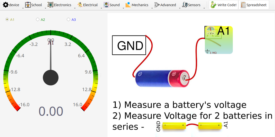
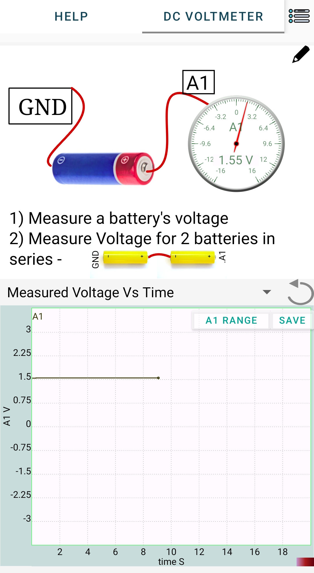
- Select one channel:
A1(orA2orA3). - Connect source negative to
GND. - Connect source positive to the selected input.
- Open the voltage-measurement tool in software.
5. Procedure
- Start with a small DC source (for example, a 1.5V cell).
- Note the reading on the selected input.
- Reverse leads once to observe sign change (
+Vbecomes-V). - For batteries in series:
- Measure one cell.
- Then measure two cells in series.
- Then measure three cells in series (if expected value is within channel limit).
- In the mobile app, you can select the voltage range by clicking on the range button at the top right corner of the graph.
- Record all readings and compare with expected sums.
6. Observation Table
| Selected Input | Source | Expected Voltage (V) | Measured Voltage (V) | Remarks |
|---|---|---|---|---|
| Single cell (1.5V) | ||||
| Two cells in series | ||||
| Three cells in series |
7. Error Analysis
Possible causes of small mismatch:
- Source internal resistance: meter loading can reduce measured voltage if it’s a very weak source.
- Input impedance effect: A1/A2 (about $1M\Omega$) load more than A3 (about $10M\Omega$).
- ADC resolution and offset: small quantization and zero-offset errors are normal.
8. Results and Discussion
- DC voltage was measured correctly on one selected input.
- Series battery voltages approximately added: \(V_{\text{series}} \approx V_1 + V_2 (+V_3)\)
- A3 generally shows less loading error for high-resistance sources.
9. Precautions
- Voltage limits are critical:
A1,A2: keep within about $\pm16V$A3: keep within about $\pm3.3V$
- Battery checks:
- 1 cell (AA): ~1.2 to 1.6V
- 2 cells in series: ~2.4 to 3.2V (safe on A3, near upper side for fresh cells)
- 3 cells in series: ~3.6 to 4.8V (do not use A3, use A1/A2)
- Use common
GND. - Do not leave input floating during observation .
10. Troubleshooting
| Symptom | Possible Cause | Corrective Action |
|---|---|---|
| Reading stays near 0V | Wrong/loose connection | Recheck GND and selected input wiring |
| Reading clipped at limit | Input over-range | Shift from A3 to A1/A2, reduce source voltage |
| Reading lower than expected | Loading by input impedance | Use A3 for high-resistance sources |
| Noisy trace | Floating input | Connect input properly to source or GND |
| Device not found | Connection issue. | Reconnect the USB cable and restart the software. |
11. Viva-Voce Questions
Q1. Why do we connect source negative to GND?
Ans: Voltage is measured relative to a reference. `GND` is that 0V reference for SEELab.
Q2. Which input is safer for 3 cells in series (~4.5V)?
Ans: `A1` or `A2`. `A3` should be kept within about $\pm3.3V`.
Q3. Why can readings differ between A1 and A3 for high-resistance sources?
Ans: Input impedance differs. A lower impedance meter loads the circuit more and can pull the measured node voltage down.
Q4. If a 3V source is connected to A1 through a 1MΩ series resistor, what will be displayed?
Ans: Model it as a divider: source -- $1M\Omega$ -- input impedance to ground. For A1, $R_{\text{in}} \approx 1M\Omega$: $$ V_{A1}=3\times\frac{1}{1+1}=1.5V $$ So the displayed voltage is approximately 1.5V.
Q5. For the same setup (3V through 1MΩ), what will A3 show if A3 input impedance is 10MΩ?
Ans: Again divider rule: $$ V_{A3}=3\times\frac{10}{1+10}=3\times\frac{10}{11}\approx2.73V $$ So A3 shows approximately 2.73V, closer to the true source voltage because of higher input impedance.