

Clock Divider using a D Flip-Flop
Adapted from the ExpEYES blog “Clock Divider” lab. A 74LS74 D flip-flop toggles on each rising clock edge when $\overline{Q}$ is tied to $D$, halving the input frequency.
1. Aim
To build a ÷2 clock divider with a D flip-flop, observe frequency halving on the oscilloscope, and verify that the output duty cycle is 50% independent of the input duty cycle.
2. Apparatus / Components Required
- SEELab3 / ExpEYES-17 (square clock source, A1, A2)
- 74LS74 dual D flip-flop
- +5 V supply for the IC (SEELab +5 V or OD1 ON)
- Breadboard and wires
3. Theory & Principle
With $D$ connected to $\overline{Q}$, each rising edge of CLK latches the complement of the previous $Q$, so $Q$ toggles. Falling edges do nothing in this edge-triggered device.
\[f_{out} = \frac{f_{in}}{2}\]Because the state spends one full input period HIGH and one LOW in the toggle sequence, $Q$ has 50% duty cycle even if the input square wave does not.
CLR and PRE (active-low) must be held HIGH for normal counting/toggling.
4. Circuit Diagram / Setup
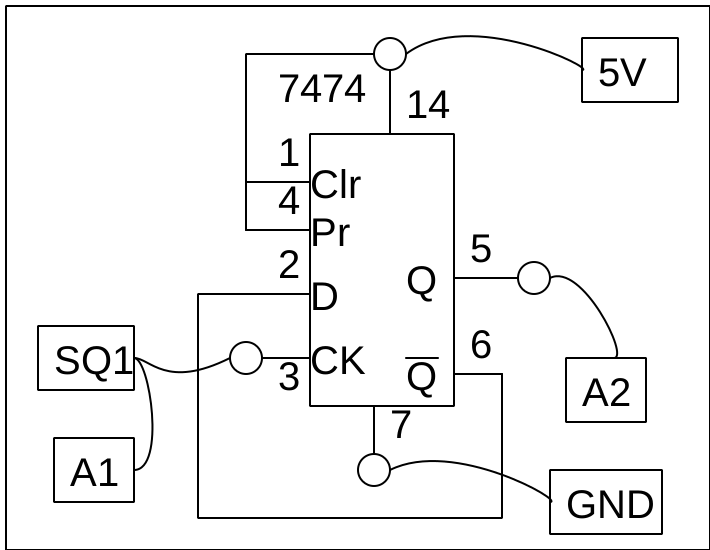
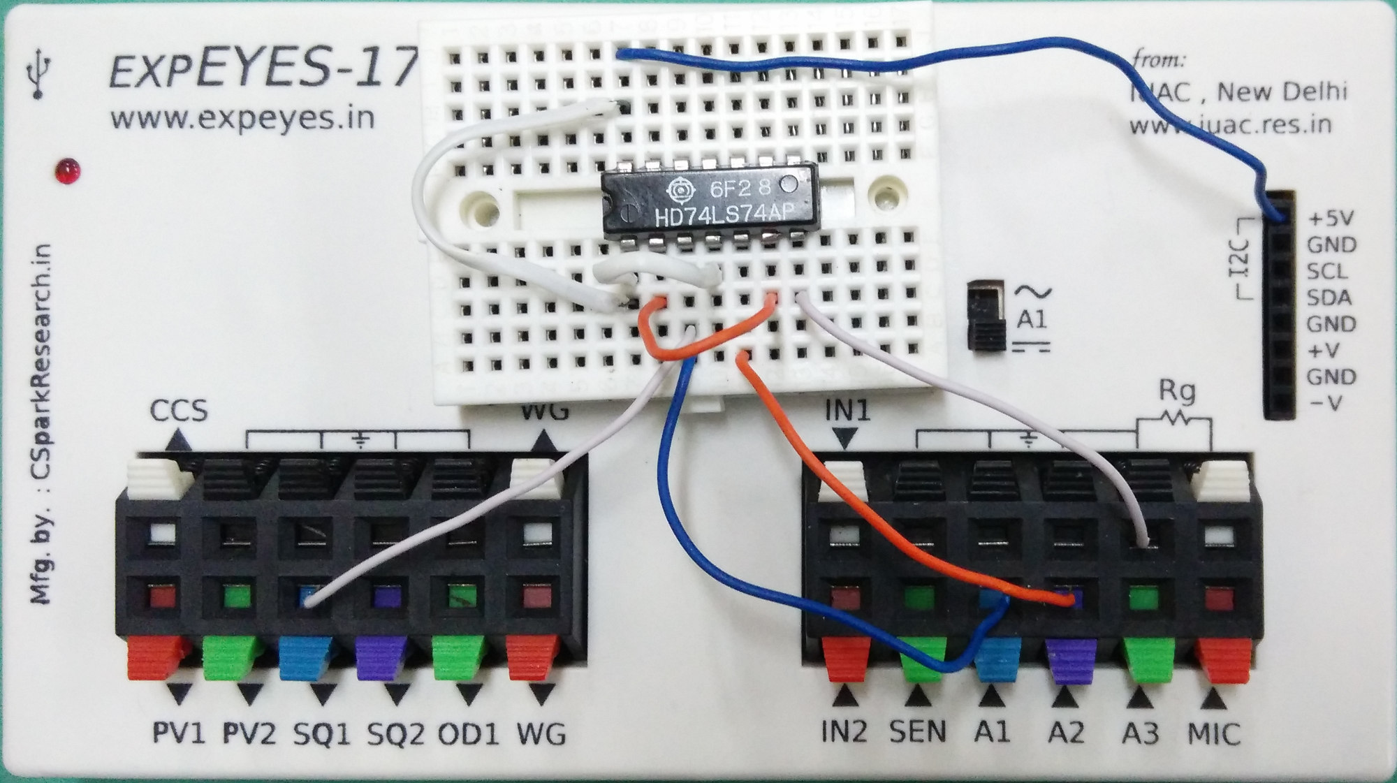
- Power 74LS74 from +5 V; common ground with SEELab.
- Apply a square wave (e.g. SQ1) to CLK.
- Connect $\overline{Q}$ → $D$.
- Tie CLR and PRE to +5 V (inactive).
- Observe CLK on A1 and $Q$ (or $\overline{Q}$) on A2.
5. Procedure
- Build the toggle wiring and hold CLR/PRE high.
- Set a square clock (try a few kHz).
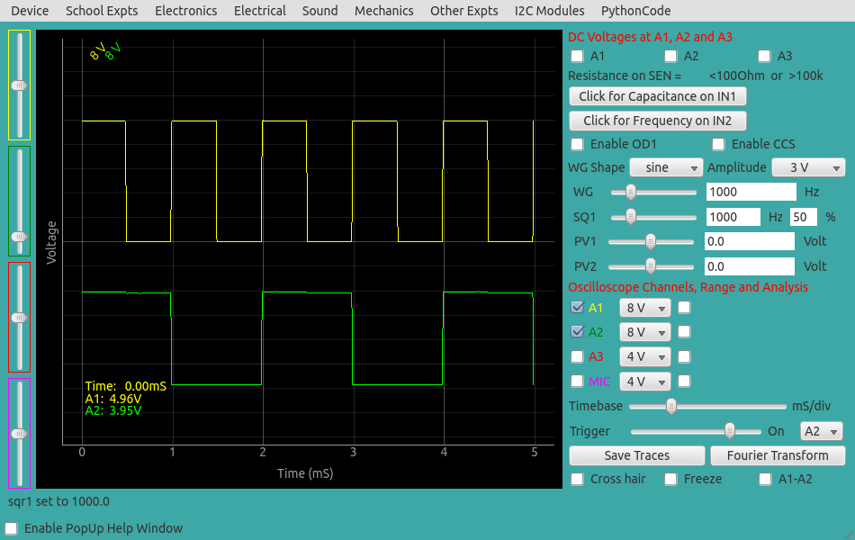
- Confirm $f_{out} \approx f_{in}/2$ from the scope time base or cursors.
- Change the input duty cycle (if your SQ source allows) and check that output duty cycle stays ≈ 50%.
- Optionally cascade a second flip-flop for ÷4.
6. Observation Table
| $f_{in}$ (Hz) | Input duty (%) | $f_{out}$ (Hz) | Output duty (%) | $f_{in}/f_{out}$ |
|---|---|---|---|---|
7. Results and Discussion
- Output frequency was half the clock frequency.
- Output duty cycle remained near 50% when input duty was varied.
- This matches edge-triggered toggle behaviour of the D flip-flop with $D=\overline{Q}$.
8. Precautions
- Hold CLR and PRE HIGH; floating async inputs cause erratic resets.
- Respect TTL voltage levels; use series resistors if feeding A3.
- Power the IC before applying a fast clock if possible.
9. Troubleshooting
| Symptom | Possible Cause | Corrective Action |
|---|---|---|
| No toggling | CLR/PRE low or floating | Tie both to +5 V |
| Same frequency as clock | $D$ not tied to $\overline{Q}$ | Check feedback wire |
| Glitches / metastability | Slow/noisy clock edges | Use clean SQ from SEELab |
10. Viva-Voce Questions
Q1. Why does $D=\overline{Q}$ produce frequency division by 2?
Ans: Each rising edge stores the opposite of the current $Q$, so two edges are needed to return to the original state — one full output period for two clock periods.
Q2. Why is output duty cycle 50%?
Ans: In the toggle sequence, $Q$ is HIGH for one clock period and LOW for the next, independent of how long the clock itself stays HIGH within each period.
Q3. What do CLR and PRE do?
Ans: They asynchronously force $Q$ LOW or HIGH. For free-running division they must be inactive (HIGH on 74LS74).