Quick Start
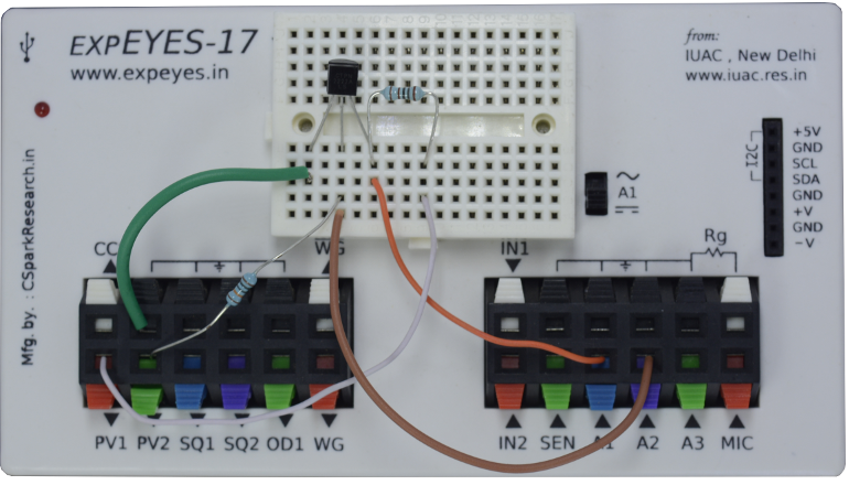
The schematic is wired as shown in the diagram below. The base current is set by the voltage from PV2, through a 100k resistor. The base voltage is measured to calculate the base current from Ib = (PV2-A2)/100K.
The collector voltage is monitored by A1. The collector is connected to PV1, through a 1k resistor.
For a selected base current, the voltage at PV1 is incremented in steps and at each step the collector voltage is measured. Corresponding collector current is calculated from i = (PV1-A1)/R. The transistor used is 2N2222, having a current gain of around 200.
Schematic

Photograph
Screenshot of the UI
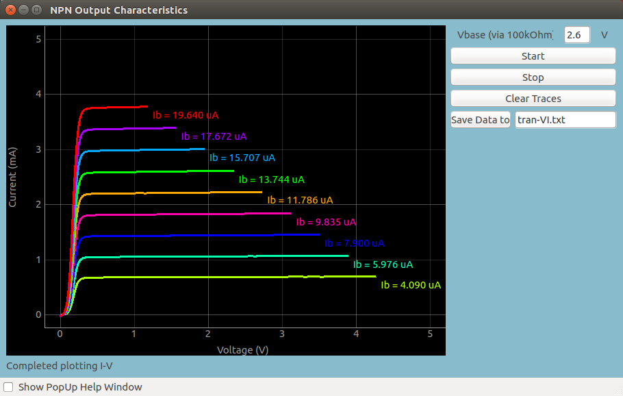
Screenshot for NPN Transistor
Screen shot of the output characteristics of an NPN Transistor in CE configuration
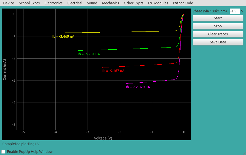
Screenshot for PNP Transistor
Screen shot of the output characteristics of a PNP Transistor in CE configuration