Quick Start
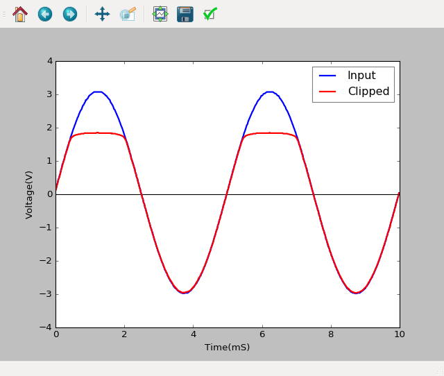
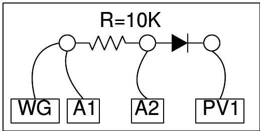
The waveform generator WG is set to give a sine wave of 1kHz. It is monitored by oscilloscope channel A1. The signal after the resistor 10K is monitored by A2.In order to clip the sine wave we are giving DC source from PV1. Since the clipped portion occurs with this circuit in the positive portion of the AC signal, it is the positive amplitude that is clipped.

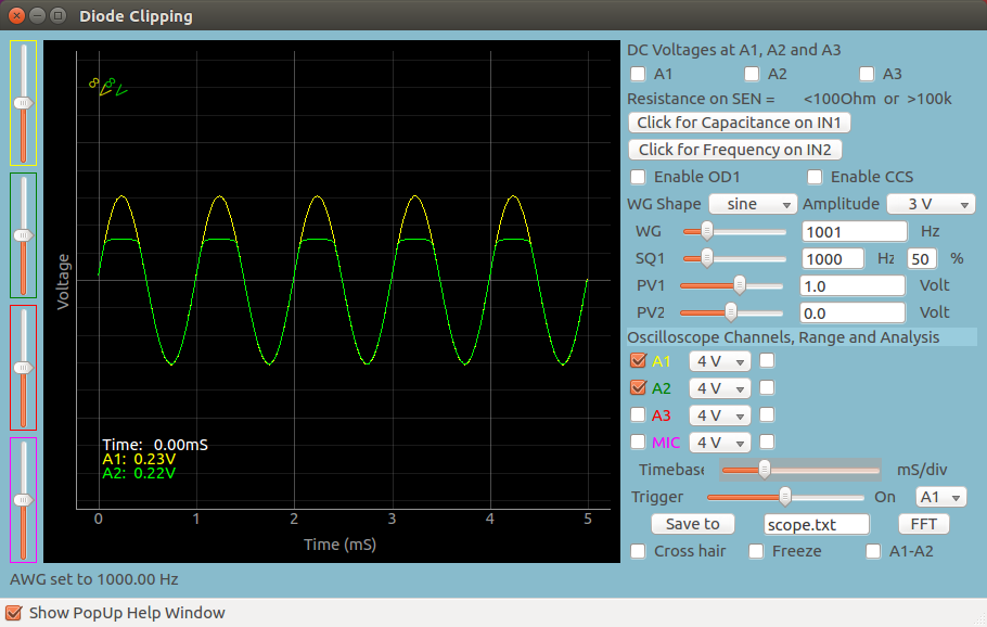
Screenshot of the UI
Screen shot of the oscilloscope program showing inputs and output of Positive Diode Clipping. 1N4148 diode at 1000Hz.
Exercises
- Play with PV1 values, and note down the clipping level and PV1 values. What is the gap between these two. Is it consistent for a particular type of diode?
- Try different diodes.
- Reverse the polarity of the diode. What effect does it have?
Write Python Code
This experiment can also be done by running this Python Code.
1
2
3
4
5
6
7
8
9
10
11
12
13
14
15
16
import eyes17.eyes
p = eyes17.eyes.open()

from pylab import *

p.set_sine(200)
p.set_pv1(1.35) # will clip at 1.35 + diode drop
t,v, tt,vv = p.capture2(500, 20) # captures A1 and A2

xlabel('Time(mS)') ylabel('Voltage(V)')
plot([0,10], [0,0], 'black')
ylim([-4,4])

plot(t,v,linewidth = 2, color = 'blue')
plot(tt, vv, linewidth = 2, color = 'red')
show()