Experiment: Measurement of the Resistance of Water
1. Aim
To measure the electrical resistance of a water column and understand why an AC voltage source is required for stable measurements in liquids.
2. Apparatus / Components Required
- SEELab3 or ExpEYES-17 unit
- Known resistor ($R_1 \approx 10\text{ k}\Omega$)
- A plastic cup or tube to hold the water sample
- Two metal electrodes (probes)
- Connecting wires
- PC or Smartphone with SEELab3 software
3. Theory & Principle
The resistivity of water is a direct indicator of its purity; dissolved salts provide ions that reduce resistivity. If you attempt to measure the resistance of water using a standard DC multimeter, the reading will not stabilize. This is due to electrolysis and chemical reactions at the electrodes, which create a back-EMF and change the ion concentration near the probes.
To obtain a stable reading, we use an AC voltage from the Waveform Generator (WG). This prevents the build-up of ions at the electrodes.
The water column is connected in series with a known resistor ($R_1$). By measuring the AC voltages across the combination and the junction, we can determine the current and the resistance of the water.
\[R_{water} = \frac{V_{A2}}{I_{R1}}\]Where $I_{R1}$ is the current flowing through the series circuit, calculated using the voltage across the known resistor ($I_{R1} = (V_{A1} - V_{A2}) / R_1$).
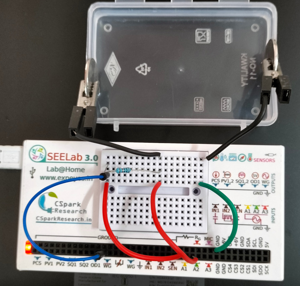
4. Circuit Diagram / Setup
- Connect a $10\text{ k}\Omega$ resistor ($R_1$) between WG and a junction point.
- Connect the water column (via electrodes) between that junction point and GND.
- Connect A1 to WG to monitor the input AC voltage.
- Connect A2 to the junction between $R_1$ and the water column.
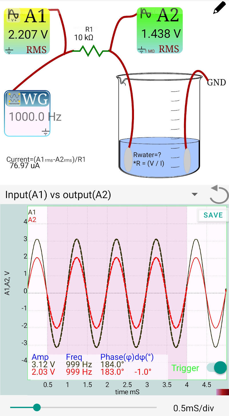
Fig A: 1000 Hz
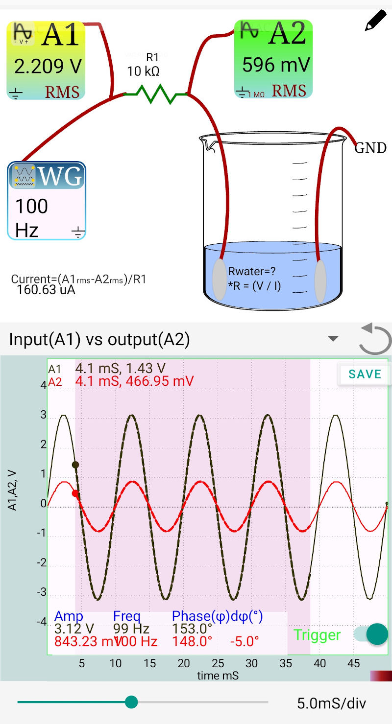
Fig B: 100 Hz
5. Procedure
- Open the SEELab3 software and select the experiment for measuring water resistance.
- Fill the container with the water sample and insert the electrodes.
- Set WG to a sine wave (e.g., $1000\text{ Hz}$).
- If the voltage ratio between A1 and A2 is extremely high, change $R_1$ to a value more comparable to the water’s resistance.
- Tap on the displayed resistor value in the app to enter the actual value of $R_1$ used.
- Select a region on the graph to analyze the waveforms. The software will display the RMS voltages and the calculated current.
6. Observation Table
Reference Resistor ($R_1$): ____ $\Omega$
| Sample | RMS Voltage A1 (V) | RMS Voltage A2 (V) | Current $I$ (mA) | Resistance $R_w$ ($\Omega$) |
|---|---|---|---|---|
| Tap Water | ||||
| Purified Water |
Example Calculation: If $V_{A2} = 1.438\text{ V}$ and $I = 0.000077\text{ A}$: $R_{water} = 1.438 / 0.000077 = 18,675\text{ }\Omega$
7. Error Analysis
In this experiment, the measurement of $R_w$ depends on the accuracy of the reference resistor $R_1$ and the voltage measurements at A1 and A2.
The percentage error in water resistance ($\frac{\Delta R_w}{R_w}$) can be estimated using: \(\frac{\Delta R_w}{R_w} \approx \frac{\Delta R_1}{R_1} + \frac{\Delta V_{A1} + \Delta V_{A2}}{V_{A1} - V_{A2}} + \frac{\Delta V_{A2}}{V_{A2}}\)
Key Factors Affecting Accuracy:
- Impedance Loading: A2 has an input impedance of $1\text{ M}\Omega$. If $R_w$ is very high (e.g., $>100\text{ k}\Omega$), A2 will act as a parallel path, leading to a lower measured resistance than actual.
- Fringing Effects: The electric field lines between probes are not perfectly straight. Using a narrow, long tube for the water column reduces this geometric error.
- Temperature Sensitivity: Water’s resistance changes by roughly 2% per degree Celsius. Ensure the water temperature is stable during measurements.
8. Results and Discussion
- The resistance of the tap water sample was found to be ____ $\Omega$.
- Using AC voltage provided a stable reading compared to a DC measurement.
- To find the specific resistance (resistivity), the dimensions of the water column (length $L$ and cross-section area $A$) must be known, using the formula $\rho = R \cdot A / L$.
9. Precautions
- Resistor Matching: For maximum accuracy, $R_1$ should be of the same order of magnitude as the water column’s resistance.
- Electrode Distance: Ensure the distance between electrodes remains constant during comparative tests.
- No DC: Do not use PV1 or PV2 for this experiment, as the DC component will cause bubble formation and steadily climbing readings.
10. Troubleshooting
| Symptom | Possible Cause | Corrective Action |
|---|---|---|
| A2 voltage is near 0V | $R_1$ is too large or water is highly conductive. | Decrease the value of $R_1$. |
| A2 voltage equals A1 | Water is acting as an insulator ($R \rightarrow \infty$). | Increase $R_1$ or add a tiny amount of salt to check the circuit. |
| Unstable waveforms | Loose electrodes. | Ensure probes are fixed and not vibrating in the liquid. |
11. Viva-Voce Questions
Q1. Why is a standard DC multimeter unsuitable for measuring the resistance of water?
Ans: When DC is applied to a liquid, it causes electrolysis. This leads to the accumulation of ions at the electrodes (polarization), creating a back-EMF and a layer of gas bubbles. This makes the resistance reading unstable and inaccurate.
Q2. How does using an AC source (like WG) solve the problem of polarization?
Ans: In AC, the direction of the current reverses periodically (e.g., 1000 times per second). This prevents the build-up of ions at the electrodes, as they are constantly being pulled back and forth, resulting in a stable resistance measurement.
Q3. What is the relationship between the concentration of dissolved salts and the resistance of water?
Ans: They are inversely proportional. As the concentration of dissolved salts (electrolytes) increases, the number of free charge carriers (ions) increases, which lowers the resistance (and increases conductivity).
Q4. What is the difference between Resistance and Specific Resistance (Resistivity)?
Ans: Resistance ($R$) depends on the shape and size of the water column. Specific Resistance ($\rho$) is an intrinsic property of the water sample itself, independent of dimensions, defined as: $$\rho = R \cdot \frac{A}{L}$$
Q5. Why do we choose a reference resistor ($R_1$) comparable to the water's resistance?
Ans: This ensures a balanced voltage divider. If $R_1$ is too large or too small compared to the water, one of the voltages ($V_{A1}$ or $V_{A2}$) will be extremely small, leading to high measurement errors due to the resolution limits of the ADC.
Q6. If you increase the distance between the two probes in the water, what happens to the measured resistance?
Ans: The resistance will increase because the length ($L$) of the conducting path has increased, and $R \propto L$.
Q7. Does the temperature of the water affect its resistance?
Ans: Yes. For most electrolytes, as temperature increases, the viscosity of the water decreases and ion mobility increases, which generally leads to a decrease in resistance.