Experiment: Summing Amplifier using Op-Amp
1. Aim
To build an inverting summing amplifier using OP07 and verify that output is proportional to the algebraic sum of input voltages.
2. Apparatus / Components Required
- SEELab3 unit
- OP07 op-amp
- $R_1 = 1\text{ kOhm}$, $R_2 = 1\text{ kOhm}$, $R_f = 1\text{ kOhm}$
- Dual supply for op-amp (about $\pm 6\text{ V}$)
- Breadboard and connecting wires
3. Theory & Principle
For an inverting summing amplifier:
\[V_{out} = -R_f\left(\frac{V_1}{R_1} + \frac{V_2}{R_2}\right)\]With $R_1 = R_2 = R_f$:
\[V_{out} = -(V_1 + V_2)\]So for $V_1 = 1\text{ V}$ and $V_2 = 2\text{ V}$, expected output is:
\[V_{out} = -3\text{ V}\]The same circuit can be tested with AC signals to observe real-time waveform addition and inversion.
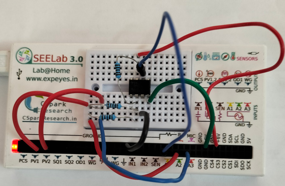
4. Circuit Diagram / Setup
- Power OP07 with dual supply.
- Ground the non-inverting input (+).
- Apply input $V_1$ (PV1) through $R_1$ to inverting node.
- Apply input $V_2$ (PV2) through $R_2$ to the same inverting node.
- Connect $R_f$ from output to inverting node.
- Measure output using A1/scope.
5. Procedure
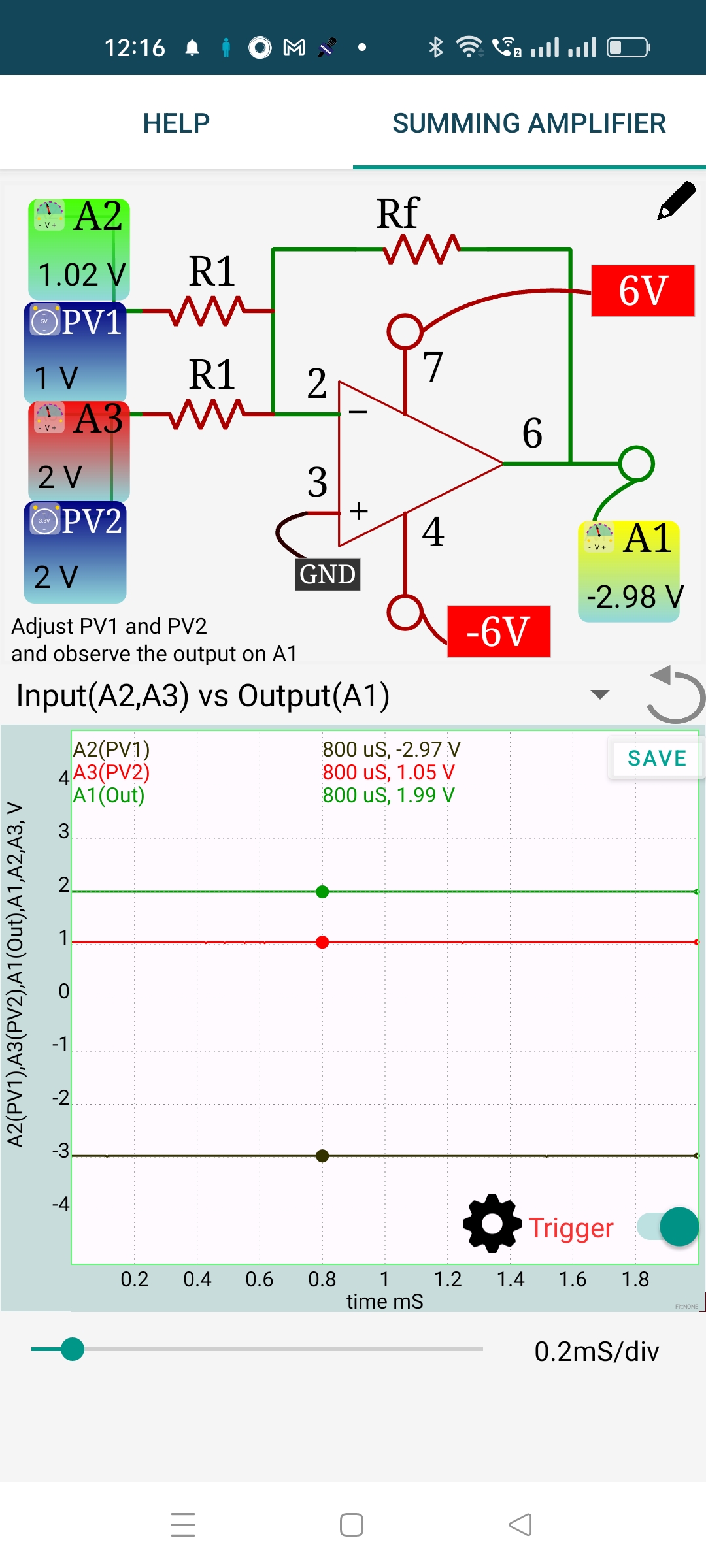
- Set PV1 = 1 V and PV2 = 2 V.
- Record output voltage and compare with theoretical -3 V.
- Repeat for multiple input pairs.
- Replace one or both DC inputs with AC signals and observe summed output.
- Increase amplitude and note clipping near supply rails.
6. Observation Table
| Trial | $V_1$ (V) | $V_2$ (V) | Expected $V_{out}$ (V) | Measured $V_{out}$ (V) | Error (%) |
|---|---|---|---|---|---|
| 1 | 1.0 | 2.0 | -3.0 | ||
| 2 | |||||
| 3 | |||||
| 4 |
7. Results and Discussion
- The circuit performed weighted addition with inversion.
- For equal resistors, measured output followed $V_{out} \approx -(V_1 + V_2)$.
- At larger input combinations, output clipping appeared near op-amp rail limits.
8. Precautions
- Ensure common ground for all input sources and SEELab3.
- Verify resistor values before power-on.
- Start with low input levels to avoid clipping.
- Check OP07 supply polarity and pinout.
9. Troubleshooting
| Symptom | Possible Cause | Corrective Action |
|---|---|---|
| Output incorrect sign | Wrong input connected to non-inverting path | Recheck inverting summing topology |
| Output not equal to sum | Wrong resistor values | Confirm $R_1$, $R_2$, $R_f$ values |
| Output clipped | Input sum too large | Reduce input amplitude/DC level |
10. Viva-Voce Questions
Q1. Why is summing amplifier output negative for positive inputs?
Ans: Because input signals are applied to the inverting terminal with negative feedback.
Q2. How does unequal resistor choice change behavior?
Ans: Each input gets a different weight: $V_{out} = -R_f(V_1/R_1 + V_2/R_2)$.