Experiment: Stroboscopic Effect and Rotational Speed
1. Aim
To demonstrate the stroboscopic effect and use a pulsed light source (LED) to “freeze” the motion of a rotating motor, thereby measuring its frequency of rotation.
2. Apparatus / Components Required
- SEELab3 or ExpEYES-17 unit
- Small DC Motor with a pulley (having a distinct dot or pattern)
- One High-Brightness White LED
- One $100\text{ }\Omega$ current-limiting resistor
- Connecting wires
- PC or Smartphone with SEELab3 software
3. Theory & Principle
The Stroboscopic Effect is a visual phenomenon caused by aliasing that occurs when continuous motion is represented by a series of short samples (light pulses).
Imagine a disc rotating at 50 revolutions per second ($50\text{ Hz}$). One full rotation takes $20\text{ ms}$. If we look at the disc under continuous light, a dot on its edge appears as a blurred circular ring due to the Persistence of Vision of the human eye (which lasts about $1/16$th of a second).
However, if we illuminate the disc with a light that flashes exactly once every $20\text{ ms}$, the dot is only visible when it is at one specific angular position. To our eyes, the rotating dot will appear perfectly stationary.
Key Relationships:
- If $f_{light} = f_{motor}$, the object appears stationary.
- If $f_{light}$ is slightly less than $f_{motor}$, the object appears to rotate slowly forward.
- If $f_{light}$ is slightly more than $f_{motor}$, the object appears to rotate slowly backward.
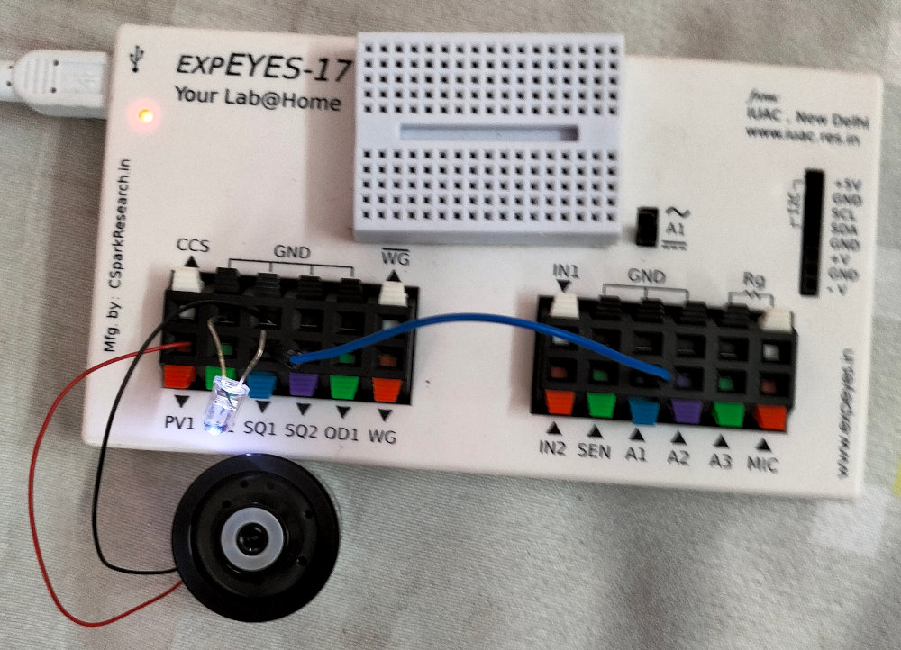
4. Circuit Diagram / Setup
- Motor Connection: Connect the DC motor between PV1 and GND.
- LED Connection: Connect the White LED in series with a $100\text{ }\Omega$ resistor between SQ1 and GND. (Ensure correct polarity: long lead of LED to SQ1). The resistor is optional only because SQ1 is internally current limited.
- Positioning: Aim the LED so it directly illuminates the pulley of the motor. Ensure the motor pulley has a clear white dot or a black-and-white pattern.
5. Procedure
- Open the SEELab3 software and select the “Stroboscope” experiment or “Oscilloscope” where you have access to SQ! frequency and duty cycle controls.
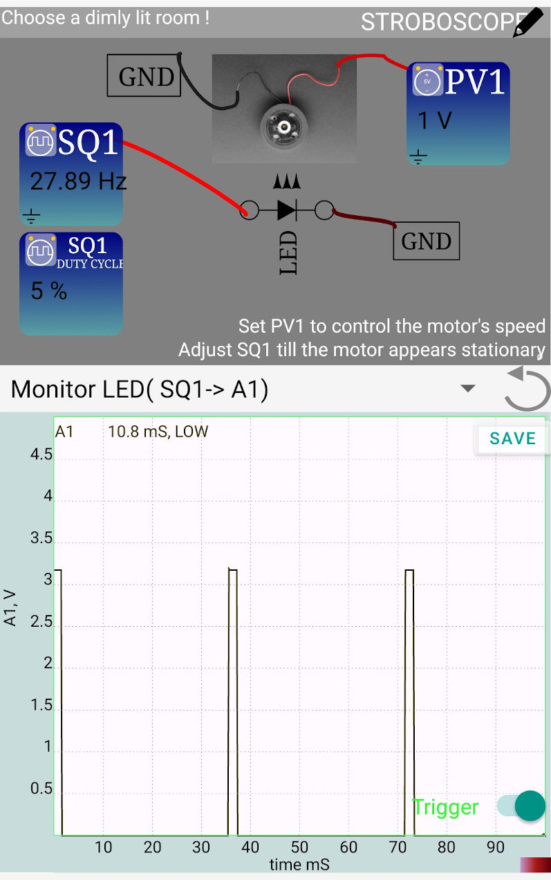
- Start the Motor: Set PV1 to approximately $1.0V$. The motor will begin to spin rapidly, and any pattern on the pulley will become a blur.
- Pulsed Light: Enable SQ1 and set the initial frequency to $10\text{ Hz}$. Adjust the “Duty Cycle” of SQ1 to a low value (e.g., $5\% - 10\%$). A short duty cycle creates sharper “flashes.”
- Find Resonance: Slowly increase the frequency of SQ1. Watch the pattern on the pulley.
- As you approach the actual frequency of the motor, the blurred pattern will begin to resolve into distinct dots.
- Fine-tune the frequency until the dots appear perfectly stationary. Record this frequency as the motor’s rotational speed in Hz.
6. Observation Table
| Motor Voltage PV1 (V) | Strobe Frequency SQ1 (Hz) | Number of Stationary Dots | Calculated Motor RPM ($f \times 60$) |
|---|---|---|---|
| 1.0 | |||
| 1.5 | |||
| 2.0 |
7. Results and Discussion
- At a specific frequency of SQ1, the rotating motor pulley appeared stationary, confirming the stroboscopic effect.
- When the strobe frequency was slightly higher than the motor frequency, the pulley appeared to rotate backward.
- The rotational speed of the motor at $1.0V$ was found to be ____ Hz, which corresponds to ____ RPM.
8. Precautions
- Duty Cycle: If the duty cycle is too high (e.g., $50\%$), the LED stays on too long per pulse, and the “frozen” image will look blurred. Keep it below $10\%$.
- Ambient Light: This experiment works best in a darkened room so that the pulsed LED light is the primary source of illumination.
- Motor Load: Do not touch the spinning pulley during measurement, as friction will change the rotational speed.
9. Troubleshooting
| Symptom | Possible Cause | Corrective Action |
|---|---|---|
| LED does not flash | Reverse polarity. | Flip the LED leads; ensure the long lead is at SQ1. |
| Multiple dots appear | Harmonic frequency. | You might be at $2\times$ or $3\times$ the motor frequency. Slow down SQ1 to find the primary frequency. |
| Motor does not spin | Voltage too low. | Increase PV1 slightly (e.g., to 1.2V) to overcome initial friction. |
10. Viva-Voce Questions
Q1. Why do we see a circular ring instead of a dot when the disc rotates fast?
Ans: This is due to Persistence of Vision. The human eye retains an image for about $1/16$th of a second. If the dot moves across many positions within that timeframe, the brain overlaps the images, creating a continuous blur.
Q2. What is the advantage of a low Duty Cycle in a stroboscope?
Ans: A lower duty cycle means the light pulse is very short. This "samples" the motor's position at a more precise instant, resulting in a much sharper, less blurred "frozen" image.
Q3. If the motor is spinning at 60 Hz and the LED flashes at 30 Hz, what will you see?
Ans: You will still see a stationary image, but you might see two dots (if there was one) or a clearer single dot depending on the alignment. Generally, sub-harmonics ($f_{strobe} = f_{motor} / n$) will also "freeze" the motion.
Q4. Why does the motor appear to rotate backward when the strobe frequency is too high?
Ans: If the light flashes slightly before the dot completes a full circle, each flash captures the dot at a position slightly "behind" its previous position. The brain interprets this sequence as backward motion.
Q5. Mention a real-life application of the stroboscopic effect.
Ans: It is used in industry to inspect high-speed machinery (like printing presses or fans) while they are running, and in "timing lights" to adjust the ignition timing of automotive engines.