Experiment: Transient Response of an RL Circuit
1. Aim
To study the transient behavior of an Inductor-Resistor (RL) circuit, observe the growth and decay of current, and determine the Inductance ($L$) by fitting the experimental data.
2. Apparatus / Components Required
- SEELab3 or ExpEYES-17 unit
- One Resistor ($R = 100\text{ }\Omega$ or $1000\text{ }\Omega$)
- One Inductor (e.g., 3000-turn coil provided in the kit)
- Connecting wires
- PC or Smartphone with SEELab3 software
3. Theory & Principle
Unlike a capacitor which opposes changes in voltage, an Inductor ($L$) opposes changes in current ($I$). When a voltage step ($V_0$) is applied to a series RL circuit, the current does not reach its maximum value ($V_0/R$) instantaneously due to the induced back-EMF.
The current growth is described by: \(I(t) = \frac{V_0}{R} (1 - e^{-t/\tau})\)
The voltage across the inductor ($V_L$) during this growth is: \(V_L(t) = V_0 e^{-t/\tau}\)
The Time Constant ($\tau$) is defined as: \(\tau = \frac{L}{R_{total}}\) Where $R_{total}$ is the sum of the external resistor and the internal DC resistance of the inductor coil.
4. Circuit Diagram / Setup
- Series Connection: Connect the Resistor ($R$) and Inductor ($L$) in series.
- Input Source: Connect one end of the Resistor to OD1 (Digital Output used for the voltage step).
- Ground: Connect one end of the Inductor to GND.
- Measurement: Connect the junction between the Resistor and Inductor to A1.
- Note: In this configuration, A1 measures the voltage across the Inductor ($V_R$).
5. Procedure
- Open the SEELab3 software and select the “RL Transient” experiment.
- The software toggles OD1 from $0V$ to $5V$ while capturing high-speed data at A1.
- Click “Capture”. You will see the current ($V_R$) rising exponentially toward a steady-state value.
- Data Analysis: Select the rising portion of the curve.
- Use the “Exponential Fit” tool. The software will calculate the time constant $\tau$.
- Measure the DC resistance of your coil ($R_L$) using the SEELab ohmmeter.
- Calculate Inductance: $L = \tau \times (R + R_L)$.

Schematic Diagram (A2 Optional)
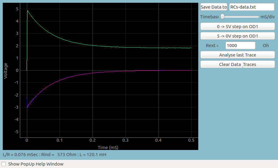
Charging and Discharge Curves
6. Observation Table
| External Resistor ($R$): ____ $\Omega$ | Coil Resistance ($R_L$): ____ $\Omega$ |
| Trial | Measured Time Constant $\tau$ (ms) | Calculated Inductance $L$ (mH) |
|---|---|---|
| 1 | ||
| 2 | ||
| Mean |
7. Results and Discussion
- The current in the RL circuit increased exponentially, confirming the presence of a back-EMF in the inductor.
- The measured inductance was found to be ____ mH.
- If a different resistor ($R$) is used, the time constant $\tau$ ____ (increases/decreases), but the calculated $L$ should remain constant.
8. Python Programming & Data
This experiment utilizes high-speed triggering to capture the sub-millisecond transition of the inductor.
9. Troubleshooting
| Symptom | Possible Cause | Corrective Action |
|---|---|---|
| Current jumps instantly | Inductance is too small. | Use a coil with more turns or lower the resistance $R$. |
| Noisy Waveform | Poor connections. | Ensure the inductor leads are making firm contact with the jumper wires. |
| Calculated $L$ is wrong | $R_L$ not included. | You MUST add the inductor’s internal resistance to the external $R$ in the formula. |
10. Viva-Voce Questions
Q1. Why does the current in an RL circuit not reach its maximum value instantly?
Ans: According to Lenz's Law, as current starts to flow, the changing magnetic field induces a back-EMF in the inductor that opposes the growth of the current.
Q2. What is the definition of the Time Constant ($\tau$) for an RL circuit?
Ans: It is the time taken for the current to reach approximately $63.2\%$ of its maximum steady-state value ($V/R$).
Q3. What is the effect of an iron core on the RL time constant?
Ans: An iron core increases the inductance ($L$). Since $\tau = L/R$, inserting an iron core will increase the time constant, making the current rise more slowly.
Q4. Why is the Inductor's DC resistance ($R_L$) important in this experiment?
Ans: Unlike an ideal capacitor, a real inductor is made of a long wire which has significant resistance. This resistance is in series with the external resistor and affects the total time constant of the circuit.
Q5. What happens to the inductor voltage at the exact moment the switch is closed ($t=0$)?
Ans: At $t=0$, the inductor acts as an open circuit (to oppose the infinite change in current). Therefore, the entire source voltage ($V_0$) appears across the inductor, and the voltage across the resistor is zero.