Experiment: Steady-State Response and Series Resonance of a Series RLC Circuit
1. Aim
To study the behavior of a series RLC circuit under a sinusoidal (AC) voltage, to measure the voltage amplitudes across each element and their phase relationships, and to observe the condition of series resonance — where the net reactive voltage across the LC combination drops to zero.
2. Apparatus / Components Required
- SEELab3 or ExpEYES-17 unit
- One Resistor ($R = 1\text{ k}\Omega$)
- One Capacitor ($C = 1\text{ }\mu F$)
- One Inductor ($L = 10\text{ mH}$, with internal DC resistance $r \approx 20\text{ }\Omega$)
- Connecting wires
- PC or Smartphone with SEELab3 / ExpEYES software
3. Theory & Principle
When a sinusoidal voltage is applied to a series RLC circuit, the inductor and capacitor each present a frequency-dependent reactance:
\[Z_L = 2\pi f L \qquad \text{(Inductive Reactance)}\] \[Z_C = \frac{1}{2\pi f C} \qquad \text{(Capacitive Reactance)}\]| Since $V_L$ leads the current by $90°$ and $V_C$ lags the current by $90°$, they are always exactly $180°$ out of phase with each other. Their net effect is the difference $ | Z_L - Z_C | $. The total impedance of the circuit is therefore: |
where $R_{eff} = R + r$ accounts for the winding resistance $r$ of the inductor.
The phase angle between the applied voltage and the current is:
\[\phi = \tan^{-1}\!\left(\frac{Z_L - Z_C}{R_{eff}}\right)\]Series Resonance
A special condition arises when $Z_L = Z_C$, i.e., when:
\[2\pi f_0 L = \frac{1}{2\pi f_0 C}\]Solving for the resonant frequency $f_0$:
\[\boxed{f_0 = \frac{1}{2\pi\sqrt{LC}}}\]At resonance:
- The net reactive impedance $(Z_L - Z_C) = 0$, so the total impedance reduces to $Z = R_{eff}$ — its minimum value.
- The current in the circuit reaches its maximum value.
- The entire applied voltage appears across $R$ — none appears across the LC combination.
- $V_L$ and $V_C$ are individually non-zero and equal in magnitude, but cancel each other exactly because they are $180°$ out of phase.
- The phase angle $\phi = 0°$ — current and applied voltage are in phase.
Note: For $L = 10\text{ mH}$ and $C = 1\text{ }\mu F$, the theoretical resonant frequency is: \(f_0 = \frac{1}{2\pi\sqrt{0.01 \times 10^{-6}}} = \frac{1}{2\pi \times 10^{-4}} \approx 1592\text{ Hz}\) The experiment starts at $1600\text{ Hz}$ and is fine-tuned to find the exact resonance point.
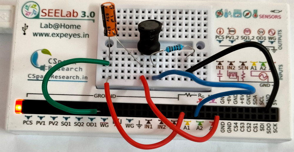
4. Circuit Diagram / Setup
- Series Connection: Connect $C$, $L$, and $R$ in series in that order.
- AC Source: Connect the free end of the capacitor to WG (Wave Generator).
- Ground: Connect the free end of the resistor to GND.
- A1 (Applied Voltage): Connect the WG end to A1.
- A3 (Voltage after C): Connect the junction between $C$ and $L$ to A3, so the software can display the voltage across the C (A1-A3) and across L(A3-A2) and detect the zero-phase condition at resonance.
- A2 (Resistor Voltage): Connect the junction between $R$ and $L$ to A2 to monitor $V_R$ directly (in phase with current).
5. Procedure
- Open the SEELab3 / ExpEYES app and select the “RLC Steady State” experiment.
- Set the wave generator (WG) to output a sinusoidal signal starting at $f = 1600\text{ Hz}$.
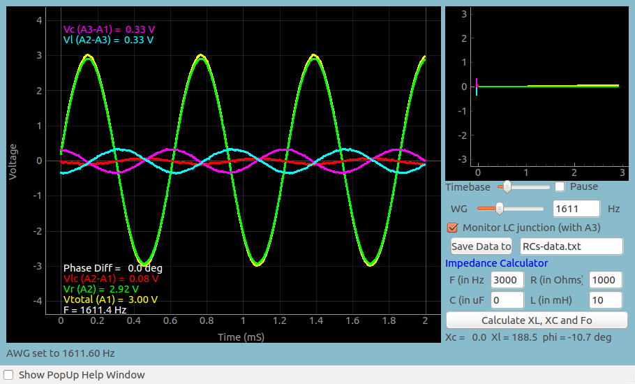
- The screen will show many traces: applied voltage, $V_R$, $V_LC$, $V_L$, $V_C$.
- Finding Resonance: Slowly vary the frequency up and down around $1600\text{ Hz}$ while watching the phase difference between A1 (applied voltage) and A2 (V_R). Resonance is reached when:
- The LC voltage trace collapses to near zero, and
- The phase difference between applied voltage and $V_R$ becomes $0°$.
- Record the resonant frequency $f_0$ from the software display.
- At resonance, note the individual amplitudes of $V_R$, $V_L$, and $V_C$ and verify that $V_L \approx V_C$ while $V_{LC} \approx 0$.
- Off-resonance sweep: Record voltages and phase angles at several frequencies below and above $f_0$ to map out the full impedance–frequency behavior.
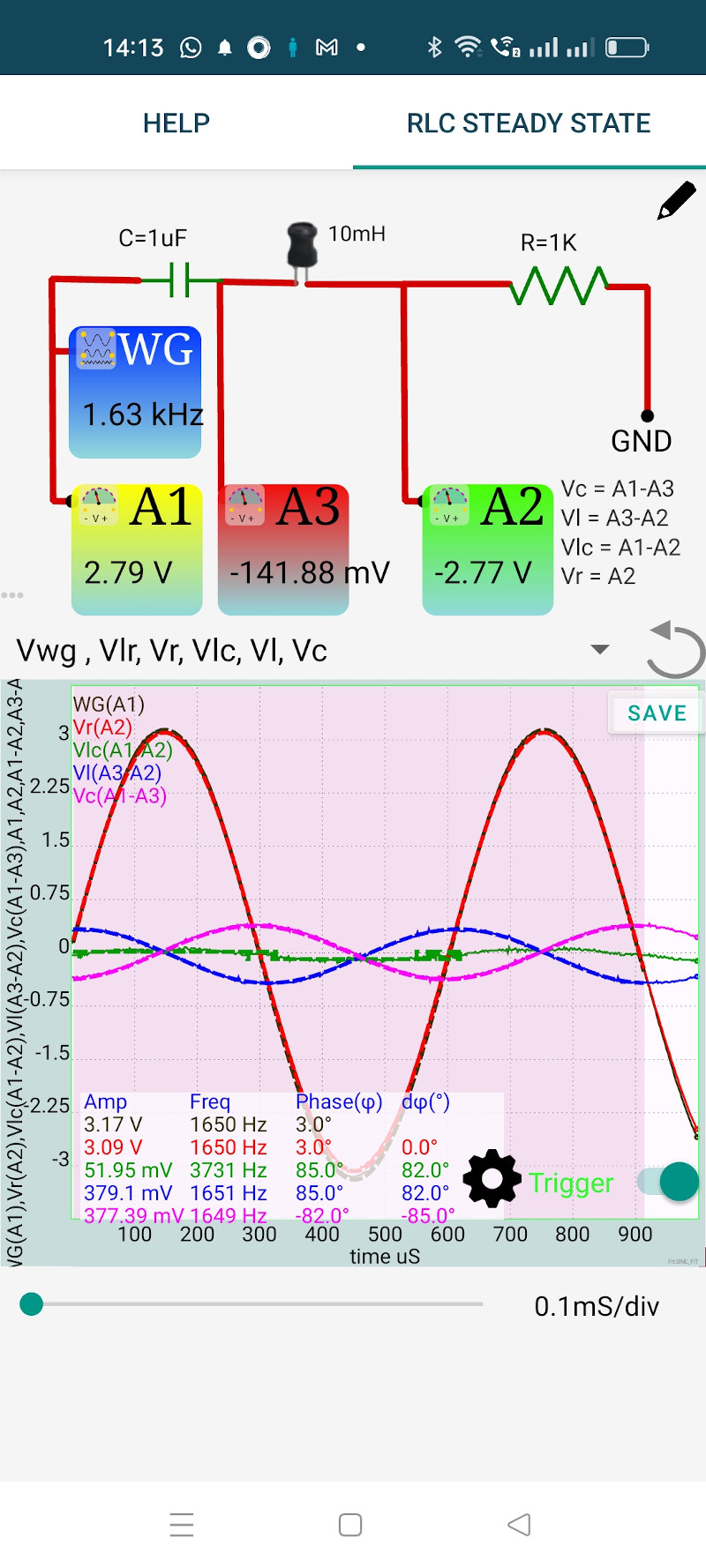
Steady State Response (Phone App)
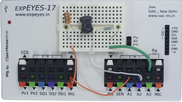
Steady State Setup For ExpEYES17
6. Observation Table
| $R$ = ____ $\Omega$ | $L$ = ____ mH | $C$ = ____ $\mu$F | $r$ = ____ $\Omega$ |
| Theoretical $f_0$ $= \dfrac{1}{2\pi\sqrt{LC}}$ = ____ Hz | Measured $f_0$ = ____ Hz |
6a. Frequency Sweep
| $f$ (Hz) | $Z_L$ ($\Omega$) | $Z_C$ ($\Omega$) | $Z_L - Z_C$ ($\Omega$) | Theoretical $\phi$ (°) | $V_R$ (V) | $V_L$ (V) | $V_C$ (V) | $V_{LC}$ (V) | Measured $\phi$ (°) |
|---|---|---|---|---|---|---|---|---|---|
| 500 | |||||||||
| 800 | |||||||||
| 1200 | |||||||||
| 1592 | |||||||||
| 2000 | |||||||||
| 3000 | |||||||||
| 5000 |
6b. At Resonance ($f = f_0$)
| Quantity | Expected | Measured |
|---|---|---|
| Phase angle $\phi$ (°) | $0$ | |
| $V_{LC}$ (net voltage across LC) | $\approx 0$ V | |
| $V_L$ (voltage across inductor) | — | |
| $V_C$ (voltage across capacitor) | — | |
| $V_R$ (voltage across resistor) | $\approx V_{applied}$ | |
| $V_L - V_C$ | $\approx 0$ V |
7. Results and Discussion
- Series resonance was observed at $f_0 =$ ____ Hz, against a theoretical value of $\approx 1592\text{ Hz}$.
- At resonance, the net voltage across the LC combination fell to approximately ____ V (ideally $0\text{ V}$), confirming that $V_L$ and $V_C$ cancel each other out.
- The individual voltages at resonance were $V_L =$ ____ V and $V_C =$ ____ V, which are nearly equal, verifying $Z_L = Z_C$ at $f_0$.
- Below resonance, the circuit was capacitive ($Z_C > Z_L$, $\phi < 0°$, current leads voltage).
- Above resonance, the circuit was inductive ($Z_L > Z_C$, $\phi > 0°$, current lags voltage).
- The phasor sum $\sqrt{V_R^2 + (V_L - V_C)^2}$ agreed closely with the directly measured applied voltage at all frequencies, verifying Kirchhoff’s Voltage Law in phasor form.
8. Precautions
- Include Winding Resistance: Always measure the DC resistance $r$ of the inductor with a multimeter and use $R_{eff} = R + r$ in all theoretical calculations to avoid a systematic error in the phase angle.
- Fine-tune for Resonance: The resonant frequency is sharp. Adjust the WG frequency in small steps (e.g., $10\text{ Hz}$ at a time) near the theoretical $f_0$ and watch for the simultaneous collapse of $V_{LC}$ and the zeroing of the phase angle.
- Component Tolerance: Capacitors and inductors may deviate from marked values by $\pm 10\%$ to $\pm 20\%$. The measured $f_0$ may differ from the theoretical value; use the measured component values if an LCR meter is available.
- Avoid Core Saturation: Do not use excessively large WG amplitudes with iron-core inductors, as nonlinearity distorts the waveforms.
- Stable Readings: Allow the waveform display to stabilize at each frequency before recording amplitudes and phase values.
9. Troubleshooting
| Symptom | Possible Cause | Corrective Action |
|---|---|---|
| Cannot find resonance near 1600 Hz | Component values differ from nominal due to tolerance. | Calculate $f_0$ using measured $L$ and $C$ values from an LCR meter; search in a wider range. |
| $V_{LC}$ never reaches zero | Winding resistance $r$ prevents perfect cancellation, or frequency resolution is insufficient. | This is normal — at resonance $V_{LC}$ reaches a minimum, not necessarily zero. Report the minimum value. |
| Phase never reaches 0° | Measurement noise or very low Q factor. | Ensure tight connections; use higher-Q components if available. |
| Waveforms are distorted | Inductor core saturating at the chosen signal level. | Reduce the WG output amplitude. |
| $V_R > V_{applied}$ | Incorrect channel assignment or probe wiring. | Recheck which nodes are connected to A1, A2, and A3. |
10. Viva-Voce Questions
Q1. What is series resonance and what is the condition for it to occur?
Ans: Series resonance occurs in an RLC circuit when the inductive reactance equals the capacitive reactance: $Z_L = Z_C$, i.e., $2\pi f_0 L = \frac{1}{2\pi f_0 C}$. At this condition the net reactive impedance is zero, the total circuit impedance is at its minimum ($Z = R_{eff}$), current is at its maximum, and the phase angle between applied voltage and current is $0°$.
Q2. At resonance, why is the net voltage across the LC combination zero even though the individual voltages $V_L$ and $V_C$ are not zero?
Ans: Because $V_L$ and $V_C$ are exactly $180°$ out of phase with each other — $V_L$ leads the current by $90°$ while $V_C$ lags it by $90°$. At resonance they are also equal in magnitude ($V_L = V_C = I \cdot Z_L = I \cdot Z_C$), so they cancel perfectly in phasor addition: $V_{LC} = V_L + V_C = 0$.
Q3. What determines the sharpness (selectivity) of resonance in a series RLC circuit?
Ans: The sharpness is determined by the Quality Factor $Q$, defined as: $$Q = \frac{f_0}{\Delta f} = \frac{Z_{L_0}}{R_{eff}} = \frac{1}{R_{eff}}\sqrt{\frac{L}{C}}$$ A high $Q$ means a narrow resonance peak — the circuit responds strongly only over a small band of frequencies. A low $Q$ (high resistance) gives a broad, flat response. This is the fundamental principle behind radio tuning circuits.
Q4. How does the circuit behave below and above the resonant frequency?
Ans: Below $f_0$: $Z_C > Z_L$, so the net reactance is capacitive — the current leads the applied voltage ($\phi < 0°$). Above $f_0$: $Z_L > Z_C$, so the net reactance is inductive — the current lags the applied voltage ($\phi > 0°$). At $f_0$ the two reactances cancel and the circuit is purely resistive ($\phi = 0°$).
Q5. Can the voltage across the inductor or capacitor exceed the applied voltage? If so, how?
Ans: Yes. At resonance, the current $I_0 = V_{applied}/R_{eff}$ is maximum. The individual element voltages are $V_L = V_C = I_0 \cdot Z_{L_0}$. Since $Z_{L_0}$ can be much larger than $R_{eff}$ (i.e., $Q \gg 1$), we get $V_L = V_C = Q \cdot V_{applied}$. This "voltage magnification" is the basis of resonant transformers and Tesla coils, and is also why high-Q resonant circuits require capacitors and inductors rated for voltages well above the supply.