Experiment: Transient Response of an RLC Circuit
1. Aim
To study the evolution of voltage across a capacitor in a series LCR circuit in response to a voltage step and to analyze the resulting damped oscillations.
2. Apparatus / Components Required
- SEELab3 or ExpEYES-17 unit
- Resistor ($R = 100\text{ }\Omega$)
- Inductor ($L = 10\text{ mH}$)
- Capacitor ($C = 0.1\text{ }\mu F$)
- Connecting wires
- PC or Smartphone with SEELab3 software
3. Theory & Principle
A series LCR circuit is a second-order system. When a voltage step ($v_s$) is applied, the relationship between the components is governed by Kirchhoff’s Voltage Law (KVL):
\[L\frac{di(t)}{dt} + Ri(t) + v_c(t) = v_s\]Substituting $i = C\frac{dv_c}{dt}$, we get the second-order differential equation:
\[\frac{d^2v_c(t)}{dt^2} + \frac{R}{L}\frac{dv_c(t)}{dt} + \frac{v_c(t)}{LC} = \frac{v_s}{LC}\]The behavior of the system depends on the roots of the characteristic equation: \(\alpha^2 + \frac{R}{L}\alpha + \frac{1}{LC} = 0\)
Depending on the values of $L$, $C$, and $R$, the response can be:
- Underdamped: $(R/2L)^2 < 1/LC$ (Oscillations that decay over time).
- Critically Damped: $(R/2L)^2 = 1/LC$ (Fastest return to steady state without oscillation).
- Overdamped: $(R/2L)^2 > 1/LC$ (Slow return to steady state without oscillation).
For the underdamped case (using the provided components), the solution is a damped sinusoid: \(v(t) = e^{\beta t} [K \sin(\gamma t + \theta)]\) Where $\beta = -R/2L$ is the damping factor and $\gamma = \sqrt{\frac{1}{LC} - (\frac{R}{2L})^2}$ is the angular frequency of oscillation.
4. Circuit Diagram / Setup
- Connect the Resistor ($R$), Inductor ($L$), and Capacitor ($C$) in series.
- Connect the free end of the Resistor to OD1 (Digital Output).
- Connect the free end of the Capacitor to GND.
- Connect A1 to the junction between the inductor and the Capacitor to measure $v_c(t)$.
5. Procedure
- Open the SEELab3 software and select the “LCR Transient” experiment.
- Click on “Step OD1 0-5V”. The software applies a $5V$ step and captures the high-speed voltage variation at A1.
- Observe the oscillating waveform. Note how the amplitude of the sine wave decreases over time.
- Analysis: Select the oscillating region on the graph.
- Use the “Damped Sine Fit” tool. The software will extract the frequency and the damping factor ($\beta$).
- Export: Save the data as a CSV file for further analysis in Python.
- Click on “Step OD1 5-0V”. The software applies a $5-0V$ step and captures the high-speed voltage variation at A1. Repeat steps 3 through 6 .
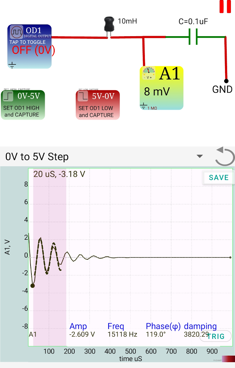
Transient Response (Phone App)
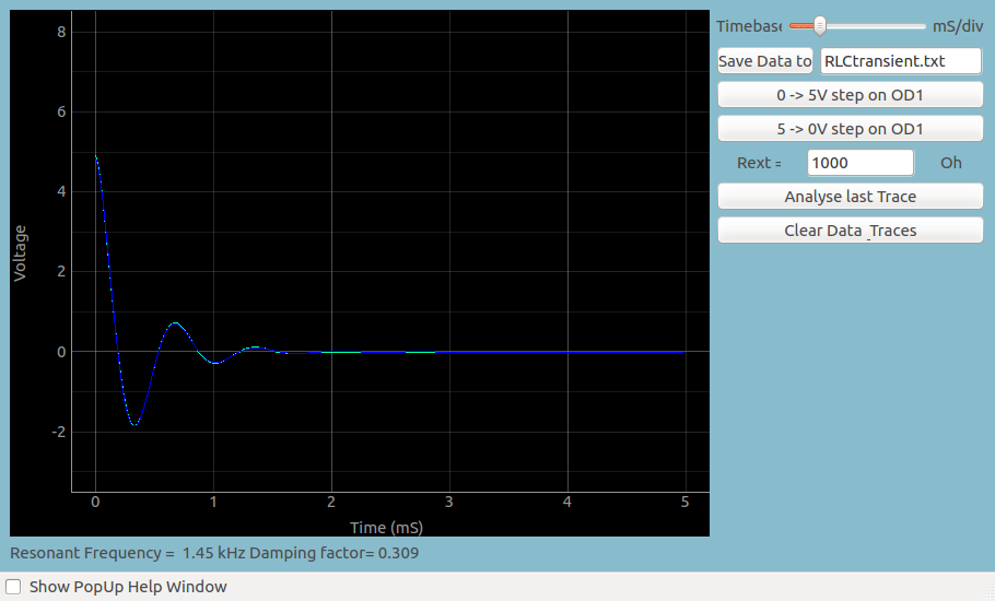
Charging and Discharge Curves
6. Observation Table
Components: $L = 10\text{ mH}$, $C = 0.1\text{ }\mu F$, $R = 100\text{ }\Omega$
| Parameter | Theoretical Value | Measured Value (from Fit) |
|---|---|---|
| Frequency ($f$) | ||
| Damping Factor ($\beta$) | ||
| Damping Ratio ($\zeta$) |
7. Results and Discussion
- The circuit exhibited _____________, as expected from the selected component values.
- The frequency of oscillation was found to be ____ Hz.
- Increasing the resistance $R$ _____ (increases/decreases) the damping, causing the oscillations to die out______ (faster/slower).
8. Python Programming & Data
- Download Python Program for LCR Transient
- Download Analysis Script (Rename exported file to
lcr.csv) - Download Sample Data
9. Troubleshooting
| Symptom | Possible Cause | Corrective Action |
|---|---|---|
| No oscillations (Flat line) | $R$ is too high (Overdamped). | Reduce $R$ to $100\text{ }\Omega$ or less. |
| Frequency is very high | $L$ or $C$ values are too small. | Ensure you are using $10\text{ mH}$ and $0.1\text{ }\mu F$. |
| Fitting fails | Not enough cycles captured. | Adjust the timebase to capture at least 3-5 full oscillations. |
10. Viva-Voce Questions
Q1. What determines whether an LCR circuit oscillates or not?
Ans: The relationship between the energy-storing components ($L, C$) and the energy-dissipating component ($R$). If the resistance is low enough ($R < 2\sqrt{L/C}$), the circuit will oscillate (As seen in the app screenshots).
Q2. What is the physical meaning of the damping factor $\beta$?
Ans: It represents the rate at which energy is lost from the circuit (as heat in the resistor). A larger $\beta$ means the amplitude of oscillations decays more rapidly.
Q3. What is the difference between "Natural Frequency" and "Damped Frequency"?
Ans: The natural frequency ($\omega_0 = 1/\sqrt{LC}$) is the frequency at which the circuit would oscillate if there were zero resistance. The damped frequency ($\gamma$) is always slightly lower than the natural frequency because of the resistance.
Q4. Why does the voltage across the capacitor eventually settle at 5V?
Ans: After the transients die out, the inductor acts as a short circuit and the capacitor acts as an open circuit to DC. Therefore, the entire source voltage ($v_s = 5V$) eventually appears across the capacitor.
Q5. What is "Critical Damping" used for in real-world applications?
Ans: Critical damping is used in systems where you want the output to reach the target value as quickly as possible without any "overshoot" or ringing, such as in analog voltmeter needles or car suspension systems.