Experiment: Frequency Response of Piezo Buzzer
1. Aim
To measure acoustic output versus drive frequency of a piezo buzzer and identify its resonant frequency region.
2. Apparatus / Components Required
- SEELab3 unit
- Piezo buzzer
- Microphone/sound sensor
- Connecting wires
- Data capture interface
3. Theory & Principle
Piezo buzzers show non-uniform response with frequency. Output intensity peaks near mechanical resonance determined by buzzer structure and enclosure.
By sweeping frequency and measuring microphone amplitude, we obtain response curve:
\[A = f(\nu)\]Peak of this curve corresponds to resonance frequency.
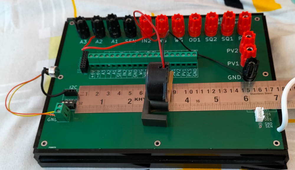
4. Circuit Diagram / Setup
- Connect piezo buzzer to waveform output.
- Place microphone at fixed distance from buzzer.
- Ensure constant geometry during sweep.
- Open frequency-response measurement screen.
5. Procedure
- Set sweep range (e.g., 1 kHz to 5 kHz).
- Run sweep and record microphone amplitude at each step.
- Plot amplitude vs frequency.
- Identify resonance peak and bandwidth around peak.
- Repeat once for consistency check.
6. Observation Table
| Frequency (Hz) | Amplitude (arb.) |
|---|---|
| 1000 | |
| 1500 | |
| 2000 | |
| 2500 | |
| 3000 | |
| 3500 | |
| 4000 | |
| 4500 | |
| 5000 |
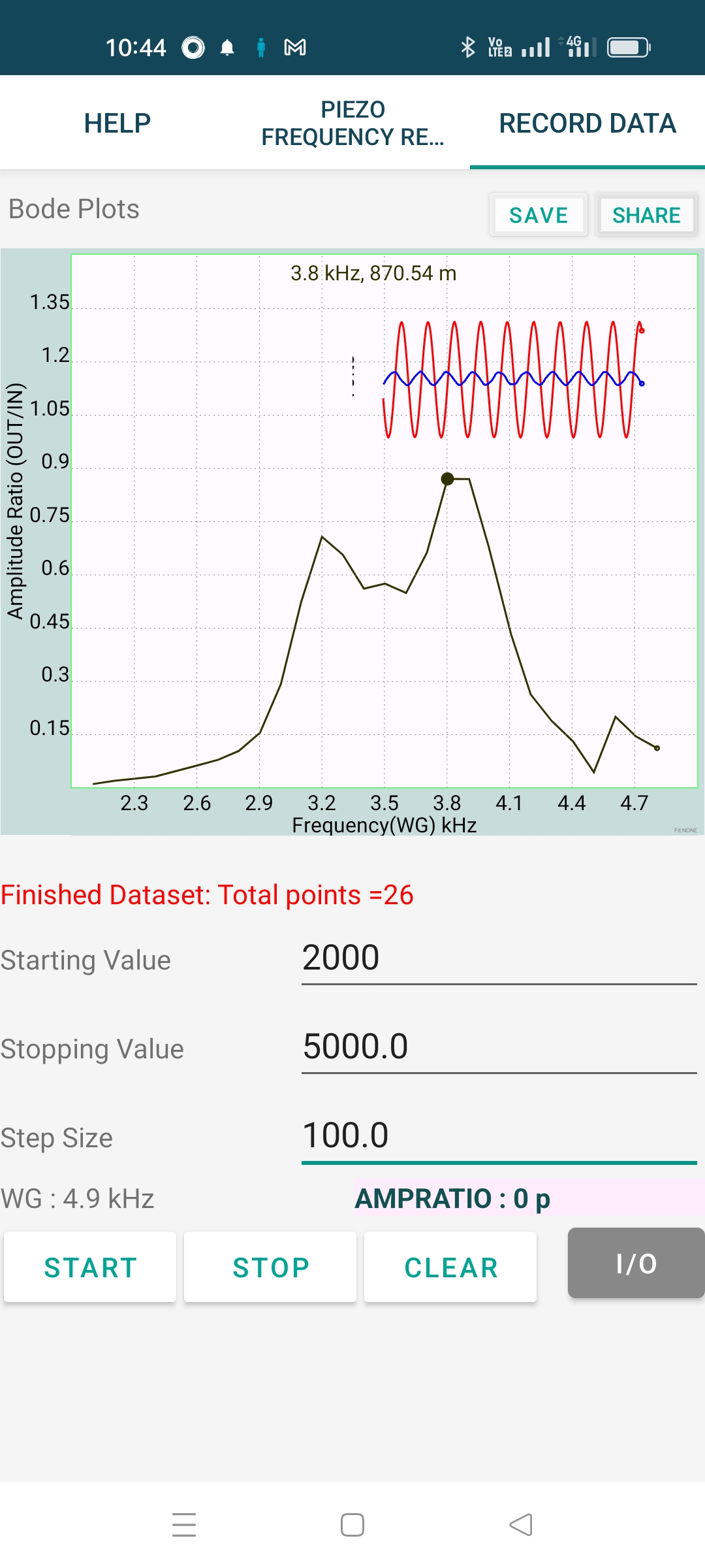
7. Results and Discussion
- Frequency response was non-uniform as expected.
- Peak response occurred near ____ Hz (resonant zone).
- Away from resonance, output amplitude dropped significantly.
8. Precautions
- Keep microphone distance fixed throughout sweep.
- Avoid reflections from nearby hard surfaces where possible.
- Use same gain settings for all readings.
9. Troubleshooting
| Symptom | Possible Cause | Corrective Action |
|---|---|---|
| Flat response curve | Microphone clipping/low sensitivity | Adjust mic gain and verify connection |
| Irregular spikes | Environmental noise/reflections | Repeat in quieter open area |
| No clear resonance | Defective buzzer or too narrow sweep | Expand sweep range and test buzzer |
10. Viva-Voce Questions
Q1. Why can't ExpEYES directly drive an 8 Ohm loudspeaker from sine output?
Ans: The source cannot supply the high current demanded by low-impedance loads; piezo is a higher-impedance alternative.
Q2. What is resonant frequency in this context?
Ans: Frequency at which buzzer mechanical-electrical coupling gives maximum output amplitude.