Experiment: Output Impedance of a Voltage Source
1. Aim
To demonstrate the concept of output impedance of a practical voltage source using the programmable DC source PV1 of SEELab3, and to determine the voltage at which the actual output begins to deviate from the set-point due to the finite output impedance of the source.
2. Apparatus / Components Required
- SEELab3 unit
- Resistor $R_L = 100\text{ }\Omega$ (load resistor)
- Connecting wires
- PC or Smartphone with SEELab3 software
3. Theory & Principle
3.1 Ideal vs Practical Voltage Source
An ideal voltage source maintains a perfectly constant terminal voltage regardless of the current drawn from it. Its output impedance is zero.
A practical voltage source, however, has a finite internal (output) impedance $Z_{out}$ in series with the ideal source. This can be modelled as:
\[V_{terminal} = V_{set} - I \cdot Z_{out}\]where $V_{set}$ is the no-load (open-circuit) set-point voltage, $I$ is the load current, and $Z_{out}$ is the output impedance. The terminal voltage $V_{terminal}$ is what actually appears at the output terminals and is always less than $V_{set}$ whenever current is drawn.
3.2 Voltage Divider Effect
When a load resistor $R_L$ is connected, the circuit forms a voltage divider between $Z_{out}$ and $R_L$:
\[V_{terminal} = V_{set} \times \frac{R_L}{R_L + Z_{out}}\]The fractional voltage drop across $Z_{out}$ is:
\[\Delta V = V_{set} - V_{terminal} = V_{set} \times \frac{Z_{out}}{R_L + Z_{out}}\]For $Z_{out} \ll R_L$ this drop is negligible and the source behaves nearly ideally. As $V_{set}$ is increased, the current $I = V_{terminal}/R_L$ increases, and the drop $I \cdot Z_{out}$ grows until the source can no longer sustain the set-point — the terminal voltage saturates.
3.3 Determining $Z_{out}$
By measuring the open-circuit voltage $V_{OC}$ (no load, $R_L = \infty$) and the loaded terminal voltage $V_L$ with a known load $R_L$, the output impedance can be calculated as:
\[Z_{out} = R_L \times \frac{V_{OC} - V_L}{V_L}\]Alternatively, from the slope of the $V_{terminal}$ vs $I$ graph:
\[Z_{out} = -\frac{\Delta V_{terminal}}{\Delta I}\]A steeper slope indicates a higher output impedance (a “weaker” source).
3.4 Current Limit and Saturation
Every practical source has a maximum current it can deliver, set by either the output impedance or an internal current-limiting circuit. Beyond the saturation point, increasing $V_{set}$ no longer raises the terminal voltage proportionally — the $V_{terminal}$ vs $V_{set}$ curve bends away from the ideal $45°$ line.
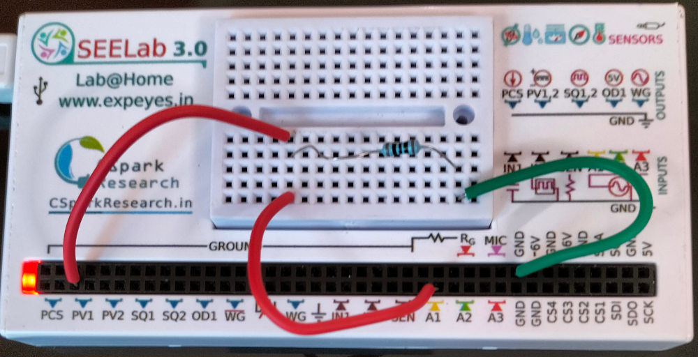
4. Circuit Diagram / Setup
- Connect one end of the load resistor $R_L$ ($100\text{ }\Omega$) to PV1 (Programmable Voltage output).
- Connect the other end of $R_L$ to GND.
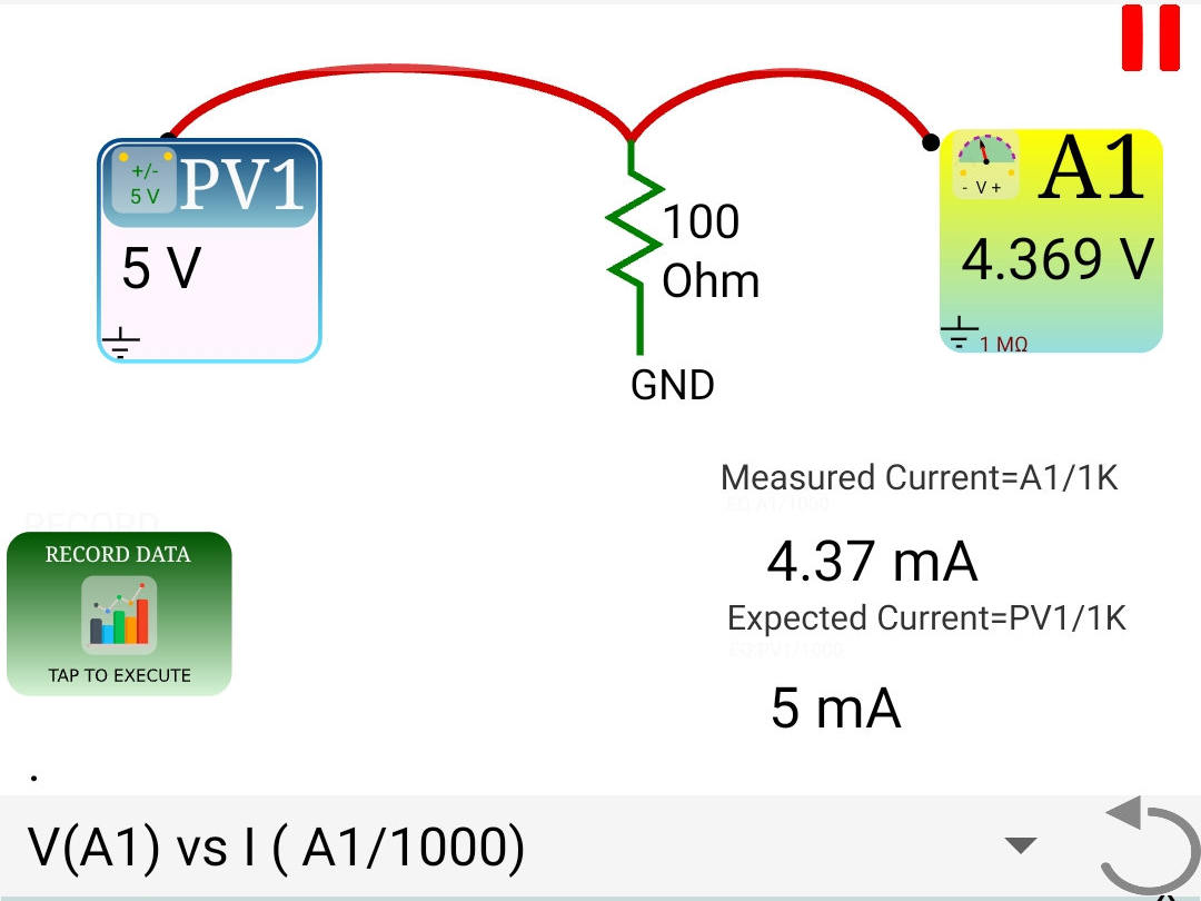
- Connect PV1 also to A1 to monitor the actual terminal voltage of the source.
The measured voltage at A1 is the true terminal voltage — it includes the effect of output impedance. The set-point is what you program in the software. Comparing the two reveals the voltage drop across $Z_{out}$.
5. Procedure
- Open the SEELab3 app and navigate to the “Output Impedance” experiment (or use the PV1 control panel directly).
- No-load measurement: Before connecting $R_L$, set PV1 to several voltages and record $V_{A1}$ each time. This establishes the open-circuit ($V_{OC}$) baseline — any deviation here is due to the input impedance of A1 ($1\text{ M}\Omega$), which is negligible.
- Connect $R_L$: Connect the $100\text{ }\Omega$ load from PV1 to GND with A1 still monitoring PV1.
- Sweep the set-point: Increase $V_{set}$ in steps from $0\text{ V}$ upward. At each step, record:
- The programmed set-point voltage $V_{set}$
- The actual terminal voltage $V_{terminal}$ read from A1
- Continue until the terminal voltage clearly stops tracking the set-point (saturation / current limit is reached).
- Plot $V_{terminal}$ vs $V_{set}$. The ideal curve is the $45°$ line $V_{terminal} = V_{set}$. Deviation from this line marks the onset of current limiting.
- Calculate $Z_{out}$ in the linear region using the formula in §3.3 at a chosen operating point.
6. Observation Table
Load Resistor $R_L$: ____ $\Omega$
6a. No-Load ($R_L$ disconnected)
| Set-point $V_{set}$ (V) | Measured $V_{OC}$ at A1 (V) | Deviation $V_{set} - V_{OC}$ (V) |
|---|---|---|
| 1.0 | ||
| 2.0 | ||
| 3.0 | ||
| 4.0 | ||
| 5.0 |
6b. Loaded ($R_L = 100\text{ }\Omega$ connected)
| Set-point $V_{set}$ (V) | Terminal voltage $V_{terminal}$ (V) | Load current $I = V_{terminal}/R_L$ (mA) | Drop $\Delta V = V_{set} - V_{terminal}$ (V) | $Z_{out} = \Delta V / I$ ($\Omega$) |
|---|---|---|---|---|
| 0.5 | ||||
| 1.0 | ||||
| 1.5 | ||||
| 2.0 | ||||
| 2.5 | ||||
| 3.0 | ||||
| 3.5 | ||||
| 4.0 | ||||
| 4.5 | ||||
| 5.0 |
7. Results and Discussion
- In the no-load condition, $V_{terminal} \approx V_{set}$ across the full range, confirming that the input impedance of A1 has negligible loading effect.
- With $R_L = 100\text{ }\Omega$ connected, the terminal voltage tracked the set-point closely at low voltages but began to deviate at $V_{set} \approx$ ____ V, indicating the onset of current saturation.
- The output impedance $Z_{out}$ was estimated to be approximately ____ $\Omega$ from the loaded measurements in the linear region.
- The maximum current deliverable by PV1 before saturation was approximately $I_{max} = V_{terminal,\text{sat}} / R_L =$ ____ mA.
- The results demonstrate that a practical source behaves ideally only when the load current is well below its current limit, i.e., when $R_L \gg Z_{out}$.
8. Precautions
- Do not short-circuit PV1: Never connect PV1 directly to GND without a load resistor. With $Z_{out}$ being small, even a short circuit draws a very large current that may damage the output stage. Always keep $R_L \geq 100\text{ }\Omega$.
- Monitor A1, not the software set-point: The set-point displayed in the software is what the firmware requests; the actual output depends on the load. Always use the A1 reading as the true terminal voltage.
- Allow settling time: After changing $V_{set}$, wait briefly for the output to settle before recording the A1 value, especially at higher currents where the internal regulator may take a moment to stabilize.
- Component power rating: At $5\text{ V}$ across $100\text{ }\Omega$, the power dissipated is $P = V^2/R_L = 250\text{ mW}$. Ensure the resistor is rated for at least $0.5\text{ W}$ to avoid overheating.
9. Troubleshooting
| Symptom | Possible Cause | Corrective Action |
|---|---|---|
| $V_{terminal}$ equals $V_{set}$ exactly at all points — no deviation | $R_L$ not connected, or wrong node monitored. | Confirm $R_L$ is wired from PV1 to GND; confirm A1 is at the PV1 terminal, not across $R_L$ alone. |
| $V_{terminal}$ drops to near zero immediately | $R_L$ too small (approaching short circuit) or PV1 current limit too low. | Replace $R_L$ with $100\text{ }\Omega$ or higher; check PV1 specifications for current limit. |
| A1 reads a negative voltage | PV1 polarity inverted or GND connection missing. | Verify GND is common between PV1, $R_L$, and the SEELab3 GND rail. |
| Erratic / noisy A1 readings | Loose connections or breadboard contact issues. | Re-seat all leads; use short, firm connections. |
10. Viva-Voce Questions
Q1. What is the output impedance of a voltage source, and what is its ideal value?
Ans: Output impedance (also called source impedance or internal impedance) is the equivalent series impedance seen looking back into the output terminals of a source. For an ideal voltage source the output impedance is zero — meaning the terminal voltage remains exactly equal to the set-point regardless of the current drawn. For an ideal current source the output impedance is infinite. Practical sources lie between these extremes.
Q2. How does output impedance cause terminal voltage to drop under load?
Ans: When load current $I$ flows, it also flows through the internal output impedance $Z_{out}$, causing a voltage drop $\Delta V = I \cdot Z_{out}$ across it. Since $Z_{out}$ is in series with the load, this drop subtracts from the set-point voltage: $V_{terminal} = V_{set} - I \cdot Z_{out}$. The heavier the load (smaller $R_L$, larger $I$), the greater the drop and the further the terminal voltage falls below $V_{set}$.
Q3. What condition must be satisfied for a practical source to behave nearly ideally?
Ans: The load resistance $R_L$ must be much greater than the output impedance $Z_{out}$, i.e., $R_L \gg Z_{out}$. Under this condition the voltage divider ratio $R_L/(R_L + Z_{out}) \approx 1$, so $V_{terminal} \approx V_{set}$. As a rule of thumb, $R_L \geq 10 \cdot Z_{out}$ keeps the voltage regulation error below approximately $10\%$, and $R_L \geq 100 \cdot Z_{out}$ keeps it below $1\%$.
Q4. How would you experimentally determine the output impedance of an unknown source?
Ans: Measure the open-circuit terminal voltage $V_{OC}$ (no load connected). Then connect a known load resistor $R_L$ and measure the loaded terminal voltage $V_L$. The output impedance is: $$Z_{out} = R_L \times \frac{V_{OC} - V_L}{V_L}$$ Alternatively, vary the load and plot $V_{terminal}$ vs $I_{load}$. The magnitude of the slope of this graph equals $Z_{out}$.
Q5. Why does increasing the set-point voltage beyond a certain point fail to increase the terminal voltage when a small load resistance is connected?
Ans: Every practical source has a maximum current it can deliver — set by the current-limiting circuitry in the output stage (or by the thermal rating of the output transistor). When this limit is reached, the regulator can no longer maintain the set-point voltage across the load: increasing $V_{set}$ merely increases the drop across the internal impedance rather than raising $V_{terminal}$. The source is said to be current-limited or saturated, and the $V_{terminal}$ vs $V_{set}$ curve bends away from the ideal $45°$ line.