Experiment: Basic Principle of Optical Communication
1. Aim
To demonstrate the conversion of electrical signals into light signals for transmission and their subsequent conversion back into electrical signals using an LED and an LDR.
2. Apparatus / Components Required
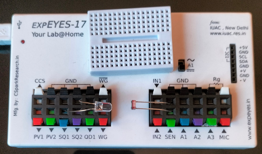
- SEELab3 or ExpEYES-17 unit
- One High-Brightness LED (White or Red) / Diode Laser
- One Light Dependent Resistor (LDR)
- Connecting wires
- PC or Smartphone with SEELab3 software
3. Theory & Principle
Optical communication involves transmitting information using light as the carrier. In this simplified demonstration:
- Transmitter: An LED acts as the source. When a pulsing electrical signal (SQ1) is applied, the LED converts these electrical pulses into flashes of light.
- Channel: The light travels through the air (or an optical fiber in practical systems).
- Receiver: An LDR acts as the detector. The resistance of the LDR decreases when light falls on it. By connecting the LDR between SEN and GND , the light pulses are converted back into a pulsing voltage signal.
While this setup uses low-frequency visible light, modern high-speed internet uses infrared lasers and fiber optic cables to transmit data over thousands of kilometers.
4. Circuit Diagram / Setup
- Transmitter: Connect the LED between SQ1 and GND. (Ensure correct polarity).
- Receiver: Connect the LDR/Phototransistor between SEN and GND.
- Alignment: Place the LED directly facing the LDR at a distance of $2\text{ cm} - 5\text{ cm}$.
5. Procedure
- Open the SEELab3 software and select the “Optical Communication” or “Oscilloscope” tool.
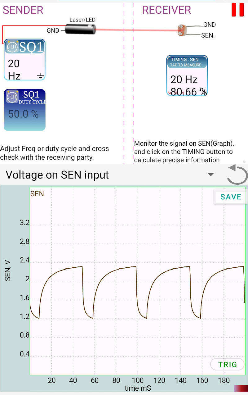
- Set SQ1 to a frequency of 20 Hz and a duty cycle of 50%. The LED should start blinking rapidly.
- Observe the waveform on the screen. You should see a square-like wave representing the light pulses detected by the LDR.
- Analysis: Tap on the SEN icon. The software will display the frequency and duty cycle of the received signal. Verify that it matches the SQ1 settings.
- Interference Test: Block the light path with a piece of paper and observe the signal disappear.
- Ambient Light: Observe how the “DC offset” of the signal changes if you perform the experiment in a dark room versus under bright tube lights.
6. Observation Table
| Source Frequency SQ1 (Hz) | Received Frequency (Hz) | Received Duty Cycle (%) | Observation |
|---|---|---|---|
| 10 | |||
| 20 | |||
| 50 |
7. Results and Discussion
- The electrical pulses from SQ1 were successfully transmitted as light pulses and recovered as electrical signals.
- The received frequency matched the transmitted frequency, demonstrating a basic communication link.
- It was observed that the “sharpness” of the received pulses decreases at higher frequencies. This is due to the slow response time (latency) of the LDR compared to the LED.
8. Precautions
- Alignment: The LED must be pointed directly at the sensitive surface of the LDR for a strong signal.
- External Light: Avoid direct sunlight on the LDR, as it can saturate the sensor and mask the LED pulses.
- Current Limit: Do not connect the LED directly to a high-voltage source; SQ1 provides a safe current for standard LEDs.
9. Troubleshooting
| Symptom | Possible Cause | Corrective Action |
|---|---|---|
| LED Not Flashing | LED polarity is reversed. | Flip the LED pins; long lead goes to SQ1. |
| Signal is very weak | Distance is too large. | Move the LED closer to the LDR. |
| Waveform looks rounded | LDR response is slow. | Decrease the frequency of SQ1 to 5Hz or 10Hz to see cleaner pulses. |
10. Viva-Voce Questions
Q1. Why do we use Light for communication instead of Copper wires?
Ans: Light has a much higher frequency than electrical signals in copper, allowing it to carry much more data (higher bandwidth). It is also immune to electromagnetic interference (EMI).
Q2. What is the role of the LDR in this circuit?
Ans: The LDR acts as a Photo-detector. it converts the variations in light intensity into variations in electrical resistance, which we then measure as a voltage change.
Q3. Why is an LDR not used in practical high-speed fiber-optic links?
Ans: LDRs have a very slow response time (they take several milliseconds to change resistance). Practical systems use Photodiodes or Phototransistors which can respond in nanoseconds.
Q4. What is 'Duty Cycle' in the context of this experiment?
Ans: Duty cycle is the percentage of time the LED is "ON" during one full cycle. A 50% duty cycle means the LED is on for half the time and off for the other half.
Q5. How would using a laser instead of a standard LED improve this experiment?
Ans: A laser produces a narrow, coherent beam of light that does not spread out as much as an LED. This would allow for communication over much longer distances with less signal loss.