Experiment: Mutual Induction and Transformer Action
1. Aim
To demonstrate the phenomenon of mutual induction between two coils and to understand the basic working principle of an AC transformer.
2. Apparatus / Components Required
- SEELab3 or ExpEYES-17 unit
- Two Solenoid Coils (e.g., 3000 turns each)
- One Ferrite or Iron core (an iron nail or bolt will also work)
- Connecting wires
- PC or Smartphone with SEELab3 software
3. Theory & Principle
Mutual induction is the process by which a changing current in one coil (the Primary) induces an Electromotive Force (EMF) in a nearby second coil (the Secondary).
This experiment combines two previously studied phenomena:
- Oersted’s Discovery: A current-carrying conductor creates a magnetic field.
- Faraday’s Law: A changing magnetic field induces a voltage across a conductor.
When an AC voltage is applied to the primary coil, it produces a continuously changing magnetic field. This field lines pass through the secondary coil, inducing an AC voltage across it. The efficiency of this energy transfer depends on the coupling between the coils.
The induced EMF ($\varepsilon_s$) in the secondary coil is given by: \(\varepsilon_s = -M \frac{dI_p}{dt}\) Where $M$ is the Mutual Inductance between the two coils.
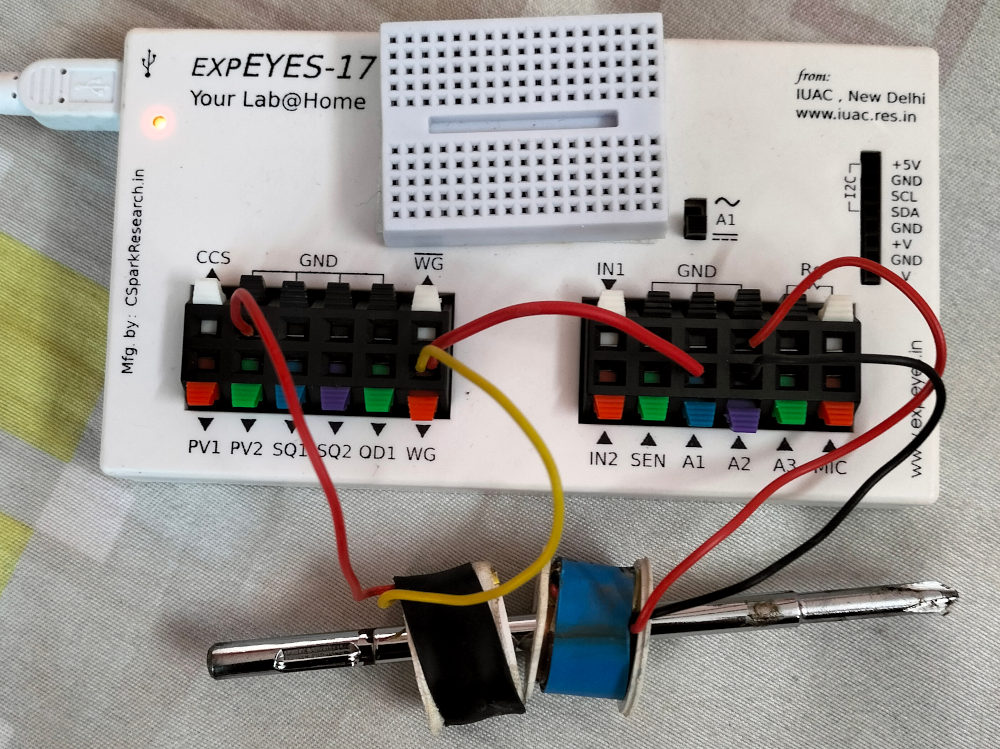
4. Circuit Diagram / Setup
- Primary Circuit: Connect one coil between WG and GND.
- Monitoring Primary: Connect A1 to WG to observe the input AC waveform.
- Secondary Circuit: Connect the second coil between A2 and GND.
- Physical Alignment: Place the two coils close to each other, coaxially.
5. Procedure
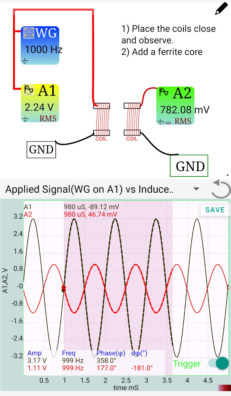
- Open the SEELab3 software and select the “Mutual Induction” or “Oscilloscope” tool.
- Set WG to a sine wave (e.g., $1000\text{ Hz}$ or $2000\text{ Hz}$).
- Observe the waveforms on A1 (Input) and A2 (Induced Output).
- Distance Test: Slowly move the coils further apart and observe the decrease in the amplitude of A2.
- Core Test: Insert a piece of magnetic material (like an iron bolt or ferrite rod) through the center of both coils.
- Observe the significant increase in the induced voltage at A2 due to improved magnetic coupling.
Mutual Inductance
6. Observation Table
| Setup Condition | Input Voltage A1 (V) | Output Voltage A2 (V) | Observation |
|---|---|---|---|
| Coils separated by 2cm | |||
| Coils touching (Air core) | |||
| Coils with Iron/Ferrite core |
7. Error Analysis
- Magnetic Leakage: In the air-core setup, most magnetic field lines do not pass through the secondary coil, leading to poor efficiency.
- Eddy Currents: If a solid iron core is used instead of a laminated core, heat losses due to eddy currents can reduce the output voltage at higher frequencies.
- Orientation: If the coils are placed at $90^\circ$ to each other, the induced EMF will drop to nearly zero because no flux lines from the primary will thread the secondary.
8. Results and Discussion
- The presence of an AC signal in the secondary coil without any direct electrical connection confirms the principle of Mutual Induction.
- Using an iron core increases the induced voltage because it has high permeability, which channels the magnetic flux more effectively from the primary to the secondary.
- This experiment demonstrates that an AC transformer requires proper geometry and core materials to be efficient.
9. Precautions
- GND Connection: Ensure both coils share a common GND terminal on the SEELab3 for stable oscilloscope readings.
- Frequency: If the frequency is too low, the rate of change of flux ($d\Phi/dt$) will be low, resulting in a very weak secondary signal.
- Core Material: Use only magnetic materials (Iron, Steel, Ferrite) for the core; materials like Aluminum or Brass will not increase the induction.
10. Troubleshooting
| Symptom | Possible Cause | Corrective Action |
|---|---|---|
| A2 signal is zero | Coils are too far or broken wire. | Bring coils closer; check coil continuity with an ohmmeter. |
| Signal is very noisy | Loose connections or EMI. | Ensure wire tips are secure; keep the setup away from power adapters. |
| A2 signal doesn’t change with core | Core material is non-magnetic. | Test the core with a permanent magnet to ensure it is attracted. |
11. Viva-Voce Questions
Q1. Define Mutual Inductance.
Ans: Mutual Inductance is the property of a pair of coils where a change of current in one coil induces an EMF in the other. It is measured in Henrys (H).
Q2. Why does inserting an iron core increase the induced voltage?
Ans: Iron has much higher magnetic permeability than air. It "concentrates" the magnetic flux lines produced by the primary coil and ensures that more of them pass through the secondary coil, increasing the coupling.
Q3. Will mutual induction work if DC is applied to the primary coil?
Ans: Only momentarily. A voltage is induced only when the magnetic flux is changing. Steady DC creates a steady magnetic field, so $d\Phi/dt = 0$ and no voltage is induced in the secondary (except at the exact moment the DC is switched on or off).
Q4. What is the "Turns Ratio" of a transformer?
Ans: It is the ratio of the number of turns in the secondary coil ($N_s$) to the number of turns in the primary coil ($N_p$). In an ideal transformer, $V_s/V_p = N_s/N_p$.
Q5. How can you minimize energy losses in a real transformer?
Ans: Losses can be minimized by using low-resistance copper wire (to reduce $I^2R$ heating), using a laminated core (to reduce eddy currents), and using a high-permeability closed-loop core (to reduce flux leakage).