Experiment: Measurement of DC Voltages on A1, A2, and A3
1. Aim
To measure and display DC voltages applied to the analog input terminals (A1, A2, and A3) of the SEELab3/ExpEYES device and to observe voltage variations over time.
2. Apparatus / Components Required
- SEELab3 or ExpEYES-17 unit
- Connecting wires
- A regulated DC power source (e.g., PV1, PV2, or a battery/cell)
- A PC, Laptop, or Android Phone with SEELab3 software
3. Theory & Principle
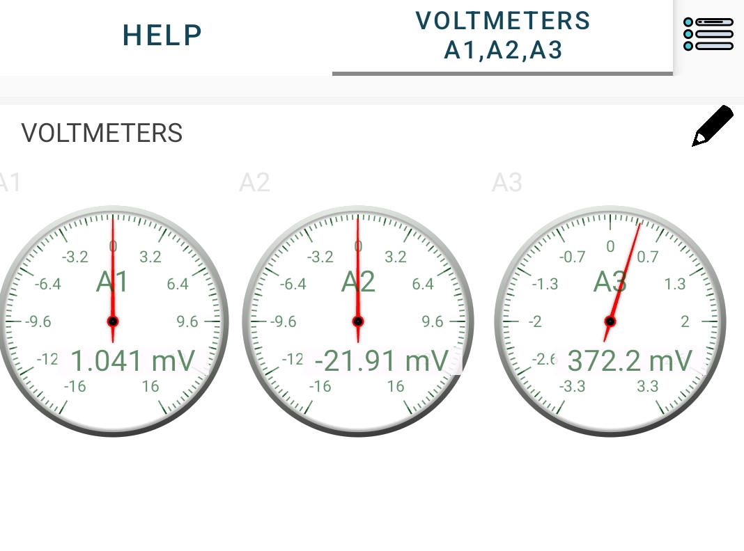
The analog inputs A1, A2, and A3 on the SEELab3 function as digital voltmeters.
- A1 and A2: Designed for general purpose use with a wider input range (typically $\pm 16V$).
- A3: Optimized for high sensitivity with a smaller range (typically $\pm 3.3V$).
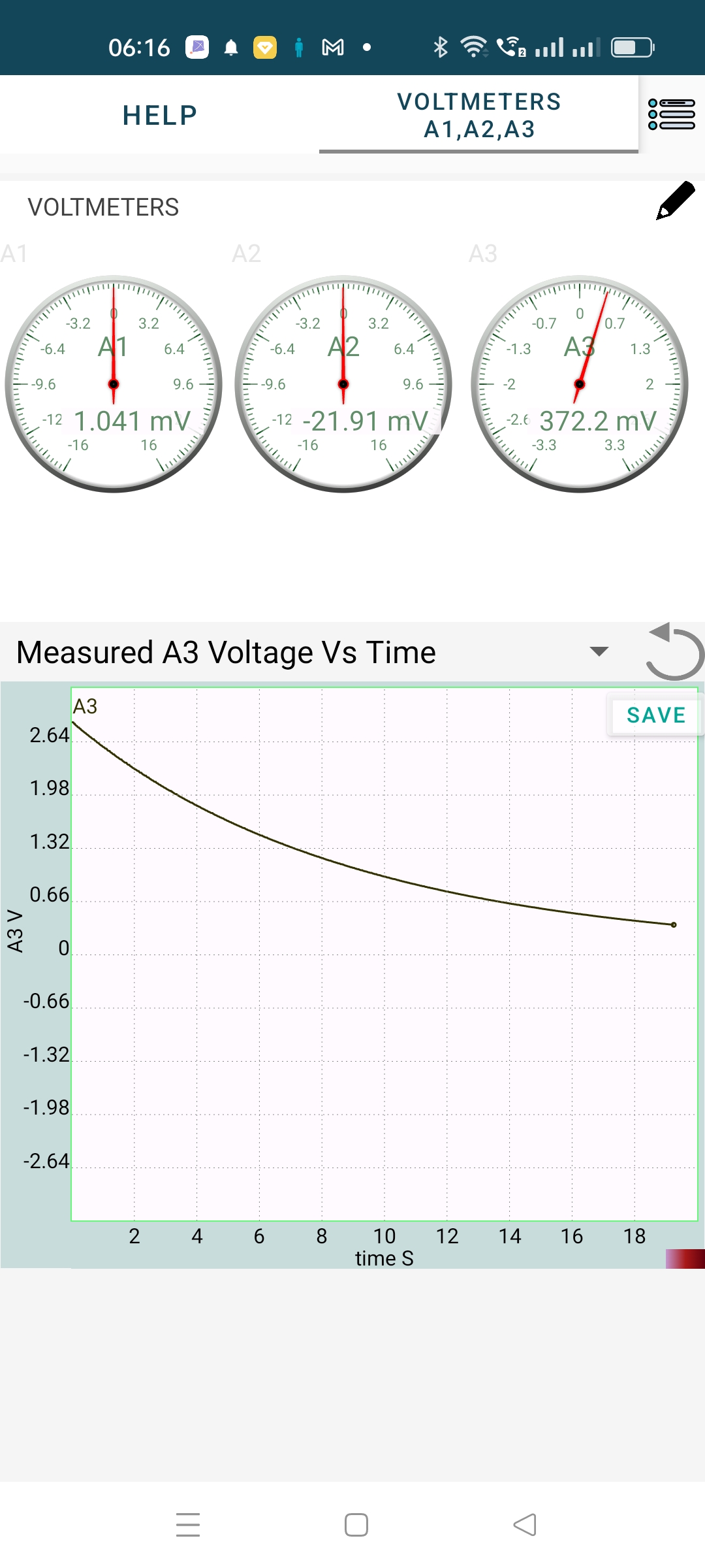
The device utilizes an Analog-to-Digital Converter (ADC) to translate continuous voltage levels into digital values. In “Multimeter” mode, the software displays instantaneous values. In “Oscilloscope” or “Plot” mode, it tracks these values over time ($t$), allowing you to visualize the stability of a DC source.
4. Circuit Diagram / Setup
- Connect the Ground (GND) terminal of the SEELab3 to the negative terminal of the voltage source.
- Connect the positive terminal of the voltage source to the A1, A2, or A3 input.
- Self-Test: You can connect PV1 to A1 to measure the voltage generated by the SEELab3 device itself.
5. Procedure
- Open the SEELab3 software and select the “Measure Voltages” or “Multimeter” experiment.
- Instantaneous View: Observe the live digital display for each channel. If using PV1 as a source, adjust the slider and watch the reading on A1 change accordingly.
- Time-Domain View: Switch to the “Plot” or “Oscilloscope” mode.
- Observe the horizontal trace. A steady DC voltage should appear as a perfectly flat line.
- Sensitivity Check: Connect a small 1.5V cell to A3 and then to A1 to compare the precision of the readings.
6. Observation Table
| Input Channel | Source Type (e.g., Battery, PV1) | Measured Voltage (V) | Remarks (Stability) |
|---|---|---|---|
| A1 | |||
| A2 | |||
| A3 |
7. Error Analysis
While digital voltmeters are highly accurate, small discrepancies can occur due to:
- Resolution Limits: The ADC has a finite number of bits. On a $16V$ range, a 12-bit ADC has a resolution of roughly $16/4096 \approx 4\text{ mV}$. Changes smaller than this cannot be detected.
- Input Impedance: A1 and A2 typically have an input impedance of $1\text{ M}\Omega$. If measuring a source with very high internal resistance, the voltmeter itself might “load” the circuit, causing a lower voltage reading.
- Zero Offset: Even with no input, the software might show a few millivolts (e.g., $0.003V$). This is a common calibration offset.
8. Results and Discussion
- The DC voltages applied to inputs A1, A2, and A3 were measured accurately.
- The software plotting feature allowed for the observation of voltage stability over the measured time interval.
- It was observed that A3 provides higher precision for low-voltage signals compared to A1.
9. Precautions
- Voltage Limits: Do not exceed $\pm 16V$ on A1/A2. Exceeding $\pm 3.3V$ on A3 may clip the signal or trigger protection circuits.
- Common Ground: The measurement is always relative to GND. Ensure the ground is common between the source and the SEELab.
- Input Floating: If nothing is connected to an input, it may “float” and show random, rapidly changing values due to electromagnetic interference.
10. Troubleshooting
| Symptom | Possible Cause | Corrective Action |
|---|---|---|
| Reading stays at 0V | Loose connection. | Check both the GND and the Input terminal wires. |
| Reading is ‘Maxed Out’ | Voltage exceeds range. | Move the connection to a channel with a higher range (e.g., A3 to A1). |
| Noisy Graph Trace | Floating input. | Connect the input to a known source or GND to see if the noise stops. |
| Device not found | Connection issue. | Reconnect the USB cable and restart the software. |
11. Viva-Voce Questions
Q1. What is the function of an ADC in SEELab3?
Ans: The Analog-to-Digital Converter (ADC) converts continuous analog voltage signals into discrete digital numbers that the computer or smartphone software can process and display.
Q2. Why is it important to connect the GND terminal?
Ans: Voltage is a measure of potential difference. The GND terminal acts as the 0V reference point. Without a common ground, the device cannot accurately determine the potential level of the input signal.
Q3. Which channel (A1 or A3) should you use to measure a 1.2V AA battery? Why?
Ans: A3 is better because it has a smaller input range ($\pm 3.3V$) and therefore offers higher resolution and sensitivity for low-voltage signals.
Q4. What does a "steady DC voltage" look like on an oscilloscope/plot?
Ans: It appears as a flat, horizontal straight line, indicating that the voltage value is constant over time.
Q5. What happens if you connect a voltage higher than 16V to A1?
Ans: The reading will "saturate" or "clip" at the maximum limit (e.g., 16.5V). While the device has protection diodes, repeatedly exceeding these limits can damage the input circuitry.