Experiment: Full-Wave Rectifier Using Two PN Junction Diodes
1. Aim
To construct a full-wave rectifier using two PN junction diodes with the SEELab3’s complementary outputs WG and $\overline{\textbf{WG}}$, to observe that both halves of the AC cycle are rectified, and to compare the output — with and without a filter capacitor — against the half-wave rectifier studied previously.
2. Apparatus / Components Required
- SEELab3 unit
- Two PN junction diodes (1N4148 or 1N4007)
- Load resistor $R_L = 1\text{ k}\Omega$
- Filter capacitor $C = 1\text{ }\mu F$
- Breadboard and connecting wires
- PC or Smartphone with SEELab3 software
3. Theory & Principle
A full-wave rectifier utilises both halves of the AC cycle, unlike a half-wave rectifier which discards the negative half. This requires two AC inputs that are $180°$ out of phase with each other — traditionally provided by the two ends of a centre-tapped transformer.
SEELab3 provides this directly through its two complementary wave generator outputs:
- WG — the primary sinusoidal output
- $\overline{\textbf{WG}}$ — the same signal inverted ($180°$ phase-shifted)
The two diodes operate in alternation:
- When WG is positive ($\overline{\text{WG}}$ negative) — D1 conducts, D2 blocks.
- When $\overline{\text{WG}}$ is positive (WG negative) — D2 conducts, D1 blocks.
In both cases current flows through $R_L$ in the same direction, so the output consists of rectified humps from every half-cycle.
The key improvements over half-wave rectification are summarised below:
| Parameter | Half-Wave | Full-Wave |
|---|---|---|
| Average DC output | $V_{peak}/\pi \approx 0.318\,V_{peak}$ | $2V_{peak}/\pi \approx 0.637\,V_{peak}$ |
| Ripple frequency | $f$ | $2f$ |
| Filter capacitor needed (same ripple) | Larger | Smaller |
| Peak output voltage | $V_{peak} - V_f$ | $V_{peak} - V_f$ |
Since the ripple frequency is $2f$, the capacitor discharges for only half the period before being recharged, giving much lower ripple for the same $RC$.
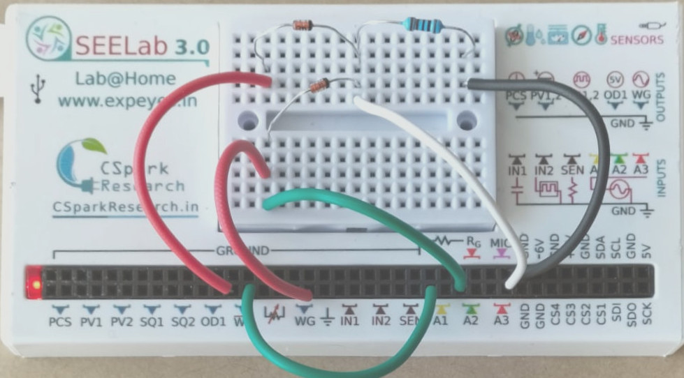
4. Circuit Diagram / Setup
- Connect the anode of D1 to WG; connect the anode of D2 to $\overline{\textbf{WG}}$.
- Connect the cathodes of both D1 and D2 together at a common node — this is the output node.
- Connect $R_L$ from the output node to GND.
- A1 monitors WG (input).
- A2 monitors $\overline{\text{WG}}$ (inverted input).
- A3 monitors the output node (across $R_L$).
For the filter stage, connect $C = 1\text{ }\mu F$ in parallel with $R_L$ after completing the unfiltered observations.
5. Procedure
- Open the SEELab3 app and select the “Full-Wave Rectifier” experiment.
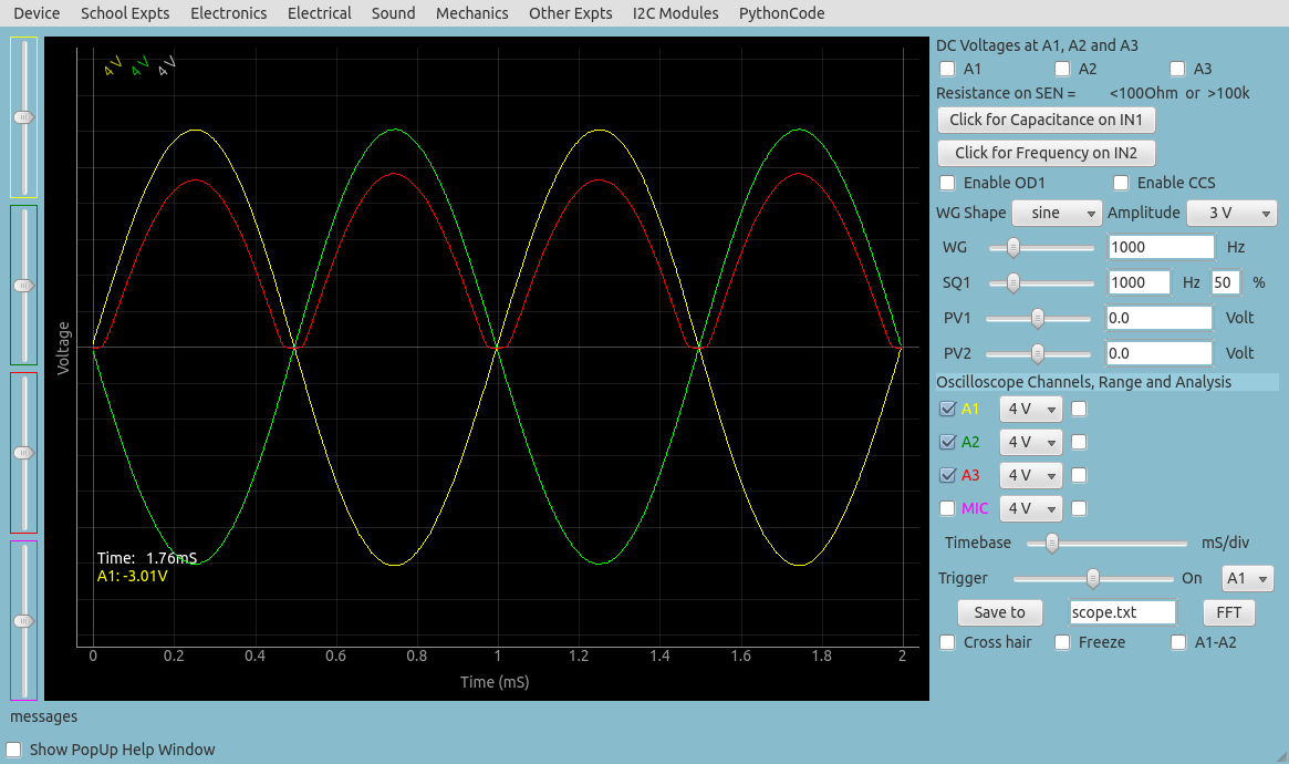
- Set WG to a sinusoidal output at $f = 1000\text{ Hz}$, amplitude $\approx 3\text{ V}$ peak.
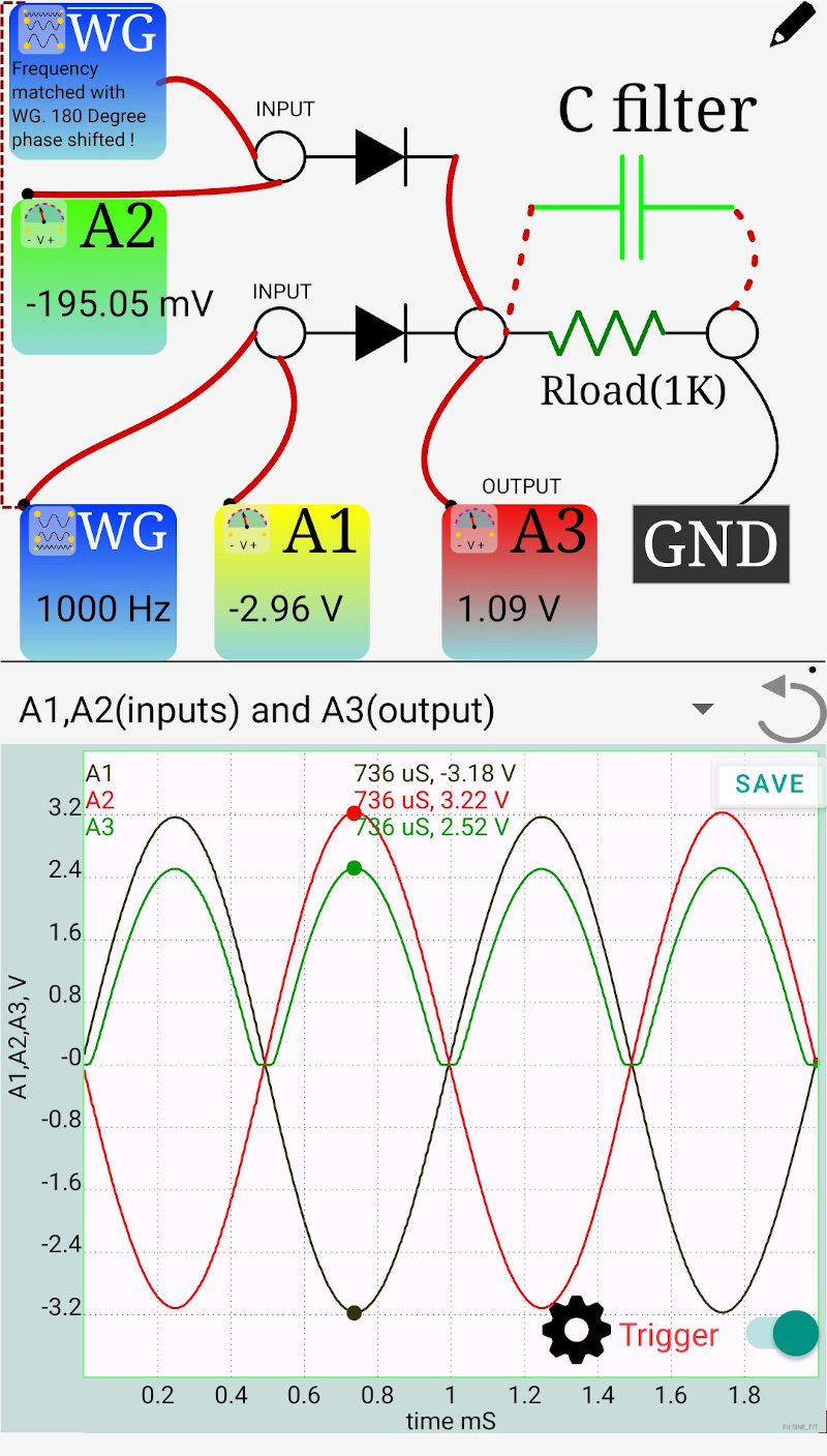
- Click “Start”. Observe the three traces on A1, A2, and A3:
- A1 and A2 should be identical sinusoids $180°$ apart.
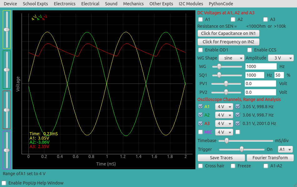
- A3 should show a full-wave rectified waveform — positive humps at twice the input frequency with no missing half-cycles.
- Record the peak output voltage and confirm the $V_f$ drop ($\approx 0.6\text{ V}$) from the input peak.
- Note the ripple frequency on A3 — it should be $2 \times 1000 = 2000\text{ Hz}$.
- Add the filter capacitor ($1\text{ }\mu F$ in parallel with $R_L$). Observe A3 again — compare the ripple amplitude and average DC level with the unfiltered output and with the filtered half-wave result from the previous experiment.
6. Observation Table
| Diodes: ____ | $R_L$: ____ $\Omega$ | Frequency: ____ Hz |
6a. Unfiltered Output
| Quantity | Measured Value |
|---|---|
| Input peak voltage $V_{in,\text{peak}}$ at A1 (V) | |
| Output peak voltage $V_{out,\text{peak}}$ at A3 (V) | |
| Forward drop $V_f = V_{in,\text{peak}} - V_{out,\text{peak}}$ (V) | |
| Ripple frequency observed at A3 (Hz) | |
| Output during negative half of A1 — present or absent? |
6b. Filtered vs Unfiltered Comparison ($C = 1\text{ }\mu F$)
| Condition | Ripple $V_{pp}$ (V) | Average $V_{DC}$ (V) |
|---|---|---|
| Full-wave, no filter | ||
| Full-wave, $C = 1\text{ }\mu F$ | ||
| Half-wave, $C = 1\text{ }\mu F$ (from previous experiment) |
7. Results and Discussion
- The output at A3 showed rectified humps for both halves of the AC cycle, confirming full-wave rectification.
- The output peak was ____ V, a drop of ____ V from the input peak due to one diode forward voltage $V_f$.
- The ripple frequency was ____ Hz — twice the input frequency of 1000 Hz — consistent with both half-cycles contributing to the output.
- With $C = 1\text{ }\mu F$, the ripple reduced to ____ V peak-to-peak and the average DC output rose to ____ V.
- Compared to the filtered half-wave result (____ V ripple), the full-wave filter produces lower ripple for the same capacitor value, because the capacitor is recharged at twice the frequency and has less time to discharge between peaks.
8. Precautions
- Diode polarity: Both cathodes must point toward the output node. A reversed diode will short one of the WG outputs to GND through a forward-biased junction.
- $\overline{\text{WG}}$ availability: The complementary output $\overline{\text{WG}}$ is a feature of SEELab3. Verify your unit has this terminal before building the circuit.
- A3 range: Ensure the output voltage stays within the safe input range of A3. With a 3 V input, the output peak ($\approx 2.4\text{ V}$) is well within range.
- Capacitor polarity: Connect the positive terminal of the electrolytic capacitor to the output node (A3 side) and negative to GND.
9. Troubleshooting
| Symptom | Possible Cause | Corrective Action |
|---|---|---|
| A3 shows only half-wave output | One diode is reversed or open. | Check both diodes with a multimeter in diode-test mode; verify cathode orientation. |
| A3 shows no output | WG or $\overline{\text{WG}}$ not connected, or both diodes reversed. | Re-check connections at both anodes and the shared cathode node. |
| Ripple frequency at A3 equals input frequency (not double) | One diode not conducting — effectively half-wave operation. | Identify and replace the faulty or backwards diode. |
| Output peak much lower than $V_{in} - 0.6\text{ V}$ | $R_L$ too small, or both diode drops in series (wiring error). | Check that the two cathodes share a single output node — not wired in series. |
10. Viva-Voce Questions
Q1. Why does a full-wave rectifier need two anti-phase AC inputs, and how does SEELab3 provide them?
Ans: Each diode in the pair can only conduct during one polarity. To ensure one diode is always forward biased regardless of the AC cycle phase, the two anodes must see voltages that are always opposite in sign. A centre-tapped transformer provides this from its two ends relative to the centre tap. SEELab3 provides the same condition digitally through its complementary outputs WG and $\overline{\textbf{WG}}$, which are identical sinusoids $180°$ apart — no transformer is needed.
Q2. Why is the ripple frequency of a full-wave rectifier twice that of a half-wave rectifier?
Ans: In a half-wave rectifier, the output produces one pulse per input cycle — once per period $T$, giving ripple at frequency $f$. In a full-wave rectifier, both the positive and negative halves of the input produce an output pulse, giving two pulses per period — ripple at $2f$. This means the filter capacitor is recharged twice as often, discharging for only $T/2$ instead of $T$ between recharge events, which substantially reduces the ripple for the same $RC$ value.
Q3. The output peak of the full-wave rectifier is $V_{peak} - V_f$, with only one diode drop. Why not two?
Ans: At any given moment, only one diode is conducting — either D1 (during the WG positive half) or D2 (during the $\overline{\text{WG}}$ positive half). The current path at any instant is: source → one diode → $R_L$ → GND. Only one diode is in the active current path at a time, so only one $V_f \approx 0.6\text{ V}$ drop appears. This is unlike a bridge rectifier, where two diodes conduct simultaneously, causing a $2V_f$ drop.
Q4. For the same filter capacitor, why does a full-wave rectifier produce less ripple than a half-wave rectifier?
Ans: The ripple voltage is approximately $V_{ripple} \approx V_{peak}/(f_{ripple} \cdot R_L C)$. Since $f_{ripple} = 2f$ for full-wave versus $f$ for half-wave, the full-wave ripple is half that of the half-wave rectifier for the same $R_L$, $C$, and input frequency. Equivalently, a full-wave rectifier needs a capacitor half the size to achieve the same ripple level.
Q5. How does this two-diode full-wave circuit differ from a bridge rectifier, and what are the trade-offs?
Ans: This circuit uses two diodes and requires a centre-tapped (or anti-phase) source, so only one diode drop ($V_f$) appears in the output path. A bridge rectifier uses four diodes but works from a single-ended AC source (no centre tap required) — however, two diodes conduct simultaneously, giving a $2V_f \approx 1.2\text{ V}$ drop. For low-voltage supplies this double drop is a significant efficiency penalty; for mains-derived supplies ($\approx 230\text{ V}$) the 1.2 V drop is negligible, which is why the bridge is more common in practice.