Experiment: Faraday’s Law of Electromagnetic Induction
1. Aim
To study the generation of an Electromotive Force (EMF) in a coil by a changing magnetic field and to verify Faraday’s Law of Induction.
2. Apparatus / Components Required
- SEELab3 or ExpEYES-17 unit
- Solenoid coil (e.g., 3000 turns)
- Strong cylindrical Neodymium magnet
- A non-magnetic tube (paper or plastic) to guide the magnet
- Connecting wires (Jumper wires with alligator clips)
- PC or Smartphone with SEELab3 software
3. Theory & Principle
Faraday’s Law of Induction states that the magnitude of the induced EMF ($\varepsilon$) in a circuit is proportional to the rate of change of magnetic flux ($\Phi_B$) through the circuit:
\[\varepsilon = -N \frac{d\Phi_B}{dt}\]Where $N$ is the number of turns in the coil. The negative sign represents Lenz’s Law, indicating that the induced current creates a magnetic field that opposes the change in flux.
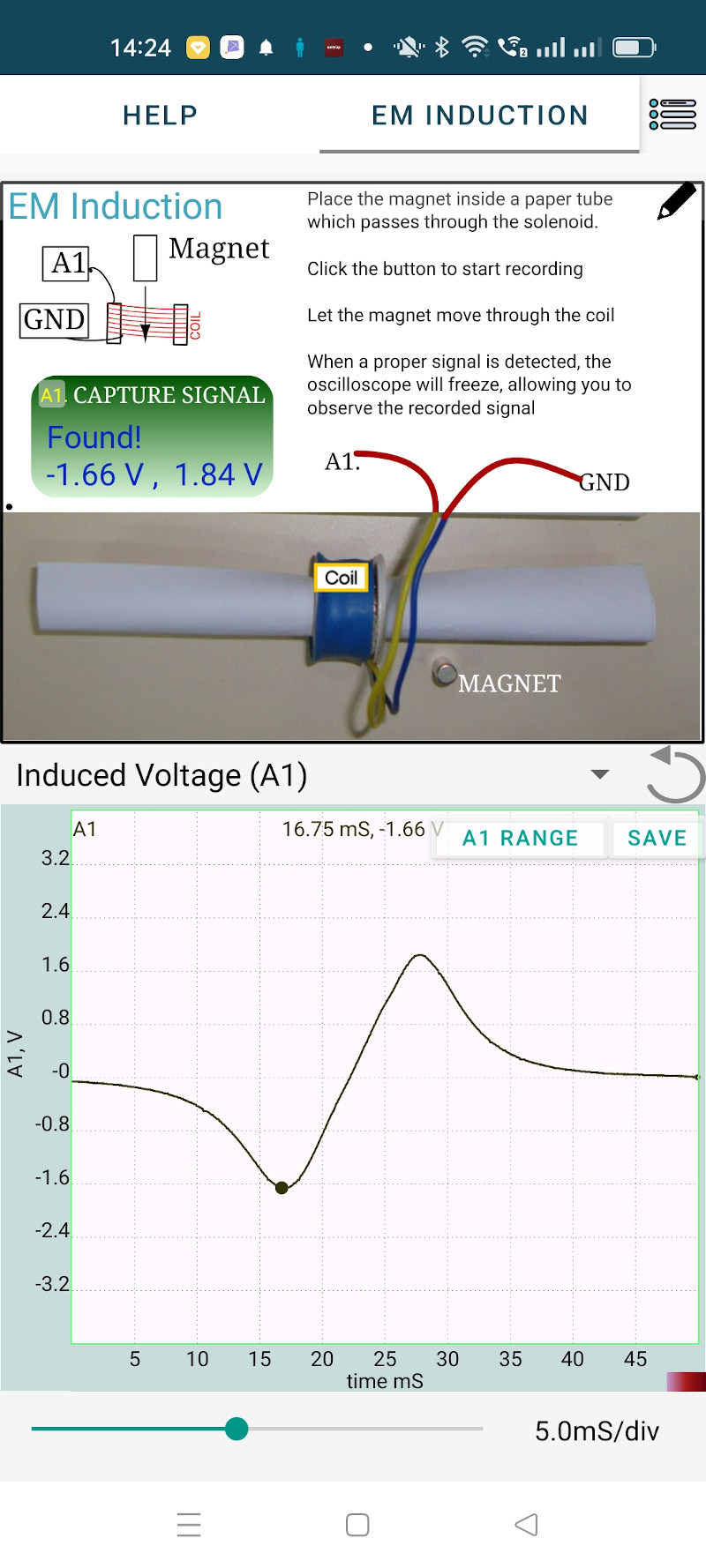
As a magnet falls through a stationary coil, the magnetic flux increases as the magnet approaches and decreases as it leaves. This results in a characteristic “double-peak” waveform. The second peak is typically larger because the magnet is accelerating due to gravity, meaning the rate of change of flux ($d\Phi_B/dt$) is higher as it exits the coil.
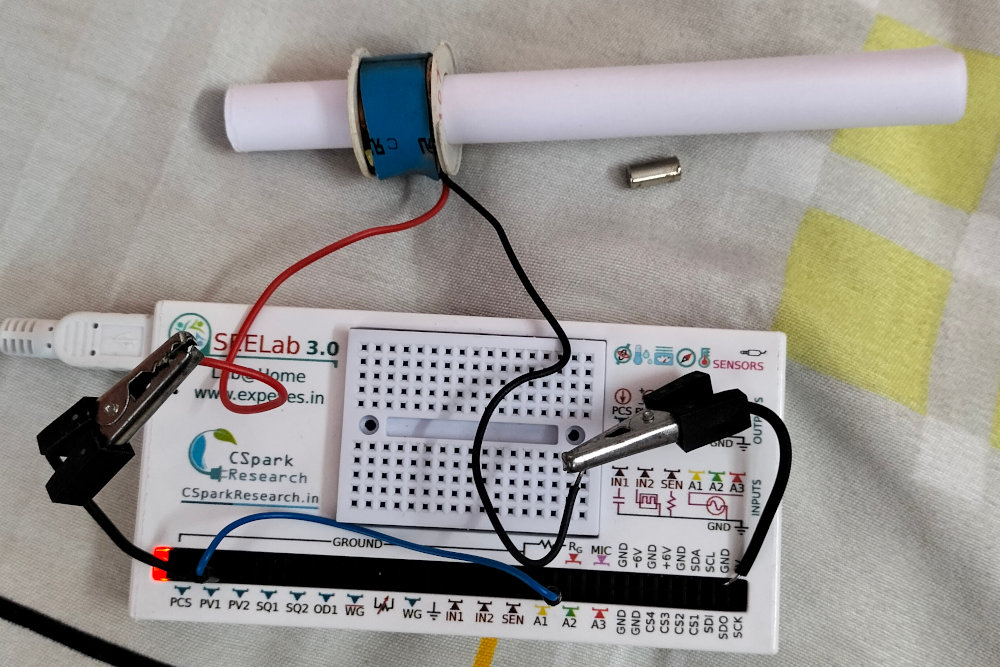
4. Circuit Diagram / Setup
- Connect the solenoid coil between A1 and GND using alligator clips.
- Ensure the non-magnetic guide tube is inserted through the center of the coil and held vertically.
- Position the coil towards the bottom of the tube so the magnet reaches a high velocity before entering.
5. Procedure
- Open the SEELab3 software and select the “Electromagnetic Induction” experiment.
- Click on “Capture Signal” or “Start” to wait for a trigger.
- Hold the magnet at the top of the tube and drop it so it passes through the center of the coil.
- The software will automatically capture and display the induced voltage waveform when the voltage exceeds the trigger threshold.
- Observe the two peaks of opposite polarity.
- Repeat: Drop the magnet from different heights and observe how the peak voltage changes with velocity.
6. Observation Table
| Drop Height (cm) | First Peak $V_1$ (V) | Second Peak $V_2$ (V) | Time Interval $\Delta t$ (ms) |
|---|---|---|---|
| 10 | |||
| 20 | |||
| 30 |
7. Error Analysis
The primary sources of error in this induction experiment include:
- Air Resistance: Drag on the falling magnet can cause it to fall slower than $g = 9.8\text{ m/s}^2$, affecting the predicted velocity.
- Magnetic Alignment: If the magnet is not perfectly centered in the tube, the flux distribution may be asymmetrical, leading to uneven peaks.
- Sampling Rate: If the magnet moves extremely fast, a low sampling rate might “miss” the exact peak voltage, resulting in lower measured values.
8. Results and Discussion
- The induced EMF shows two peaks because the flux increases as the magnet enters and decreases as it leaves.
- The second peak is larger than the first because the magnet is moving faster due to gravitational acceleration ($v = \sqrt{2gh}$).
- The area under the voltage-time curve ($\int V dt$) represents the total change in magnetic flux.
9. Precautions
- Alignment: Ensure the magnet falls straight through the center of the coil without hitting the sides for a clean waveform.
- Triggering: If the software fails to capture, check the trigger level settings; it should be set slightly above the noise floor.
- Coil Orientation: The polarity of the peaks (which one is positive/negative) depends on which pole of the magnet enters first.
10. Troubleshooting
| Symptom | Possible Cause | Corrective Action |
|---|---|---|
| No signal captured | Trigger level too high or wires loose. | Lower the trigger threshold or check the GND/A1 connections. |
| Very small peaks | Weak magnet or slow drop. | Use a Neodymium magnet or increase the drop height. |
| Signal is saturated | Induced voltage exceeds input range. | Increase the drop height further or use a coil with fewer turns. |
11. Viva-Voce Questions
Q1. What happens to the induced EMF if the number of turns in the coil is doubled?
Ans: According to Faraday's Law ($\varepsilon = -N d\Phi/dt$), the induced EMF is directly proportional to the number of turns. Therefore, doubling the turns will double the induced voltage.
Q2. Why are the two peaks in the waveform of opposite polarity?
Ans: As the magnet approaches, the flux is increasing ($+d\Phi/dt$). As it leaves, the flux is decreasing ($-d\Phi/dt$). Since the direction of change in flux reverses, the direction of the induced EMF also reverses.
Q3. Explain Lenz's Law in the context of this experiment.
Ans: Lenz's Law states that the induced current will flow in a direction that creates a magnetic field opposing the motion of the magnet. This means the coil exerts a magnetic "braking" force on the falling magnet if shorted.
Q4. Why is the second peak usually taller and narrower than the first?
Ans: Because the magnet is accelerating due to gravity, it exits the coil faster than it entered. A higher velocity means a faster rate of change of flux ($d\Phi/dt$), resulting in a higher voltage peak over a shorter duration of time.
Q5. What would happen if you dropped a non-magnetic material (like a piece of wood) through the coil?
Ans: No EMF would be induced. A changing magnetic flux is required to induce a voltage, and a non-magnetic material does not provide a magnetic field.
Q6. The peaks have flat tops instead of rounded. what could be the reason?
Ans: Magnet moved fast enough to generate voltage exceeding the 16V limit of A1 input, causing it to be clipped .