Experiment: Pulse Width and Duty Cycle Measurement
1. Aim
To measure the frequency and duty cycle of a square wave signal using the digital frequency counter input (IN2) and to observe the effect of pulse-width modulation.
2. Apparatus / Components Required
- SEELab3 or ExpEYES-17 unit
- Connecting wires
- PC or Smartphone with SEELab3 software
3. Theory & Principle
A square wave is characterized by its Frequency (how many cycles per second) and its Duty Cycle (the percentage of time the signal remains in the “High” state).
The Duty Cycle ($D$) is calculated as: \(D = \frac{T_{on}}{T_{total}} \times 100\%\)
Where:
- $T_{on}$ is the time the signal is at high level (Pulse Width).
- $T_{total}$ is the total time for one full cycle ($T_{on} + T_{off}$).
The IN2 terminal on the SEELab3 acts as a high-speed digital timer. It measures the time interval between a rising edge and a falling edge ($T_{on}$) and between two consecutive rising edges ($T_{total}$) to calculate the duty cycle accurately.
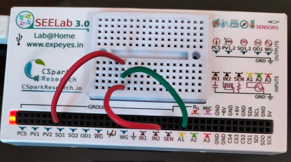
4. Circuit Diagram / Setup
- Signal Source: Connect SQ1 to IN2.
- Monitoring: Connect SQ1 to A1 so you can visually confirm the waveform on the oscilloscope.
- Note: The digital inputs (IN2, SEN) expect a “Logic Level” signal. The Low level should be $0V$, and the High level should be between $3V$ and $5V$.
5. Procedure
- Open the SEELab3 software and select the “Duty Cycle” or “Frequency Counter” tool.
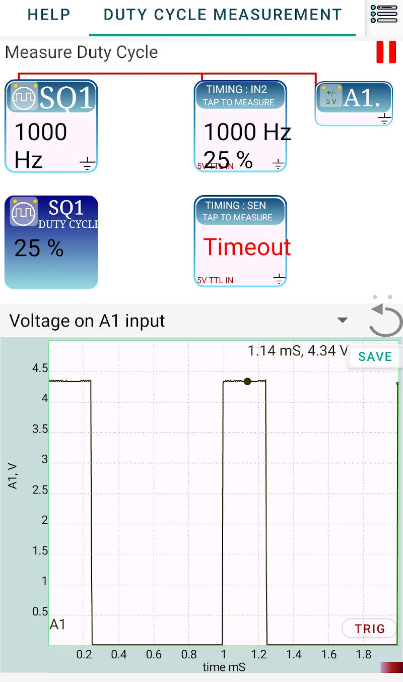
- Set the Source: In the Waveform Generator panel, set SQ1 to a frequency (e.g., $1000\text{ Hz}$) and an initial duty cycle of 50%.
- Measure: Tap or click on the IN2 icon in the software interface. The device will perform the timing measurement and display the Frequency and Duty Cycle.
- Vary the Width: Change the duty cycle of SQ1 to 20% and then 80%. Re-measure using the IN2 icon and observe how the $T_{on}$ width changes on the A1 trace.
- Timeout Check: Disconnect the wire from IN2 and try to measure again. The software will report a “Timeout” because it cannot find the signal edges.
6. Observation Table
| Set Frequency (Hz) | Set Duty Cycle (%) | Measured Frequency (Hz) | Measured Duty Cycle (%) |
|---|---|---|---|
| 1000 | 50 | ||
| 1000 | 20 | ||
| 1000 | 80 | ||
| 5000 | 50 |
7. Results and Discussion
- The frequency and duty cycle of the signal from SQ1 were accurately measured by the IN2 terminal.
- It was observed that the $1000\text{ Hz}$ frequency remained constant while the pulse width varied according to the duty cycle setting.
- The “Timeout” error confirms that the digital timer requires a continuous series of pulses (edges) to perform a calculation.
8. Precautions
- Voltage Levels: Do not apply more than $5V$ to the IN2 or SEN terminals, as these are digital logic inputs.
- Grounding: Ensure a clean common ground to avoid “triggering” on electrical noise, which could lead to incorrect frequency readings.
- Frequency Limits: For very high frequencies, the precision of the duty cycle measurement may decrease due to the internal clock resolution of the microcontroller.
9. Troubleshooting
| Symptom | Possible Cause | Corrective Action |
|---|---|---|
| “Timeout” Error | No signal or wire loose. | Check connection between SQ1 and IN2; ensure SQ1 is turned ON. |
| Reading is unstable | Noise on the line. | Use shorter wires; keep away from AC power adapters. |
| Frequency is correct, but Duty is 0% | Signal is always LOW. | Check if SQ1 is set to 0V or if there is a short to GND. |
11. Viva-Voce Questions
Q1. What is the difference between Period and Frequency?
Ans: Frequency ($f$) is the number of cycles per second (Hz). Period ($T$) is the time taken for one full cycle (seconds). They are related by $f = 1/T$.
Q2. What is 'Pulse Width Modulation' (PWM)?
Ans: PWM is a technique of encoding information or controlling power by varying the duty cycle (width) of a square wave while keeping the frequency constant.
Q3. What happens to the 'average voltage' of a 5V square wave as the duty cycle increases?
Ans: The average (DC) voltage increases. $V_{avg} = V_{peak} \times \text{Duty Cycle}$. At $50\%$, it is $2.5V$; at $100\%$, it is $5V$.
Q4. Why does the software show a "Timeout" when the wire is disconnected?
Ans: The measurement algorithm waits for a "Rising Edge" to start its timer. If no signal is present, the edge never occurs, and the software stops waiting after a certain period (Timeout) to prevent the program from freezing.
Q5. Mention one practical application where Duty Cycle control is used.
Ans: It is used in DC motor speed controllers, LED dimmers, and switching power supplies (SMPS) to regulate output efficiently.