Experiment: Distinction Between AC and DC
1. Aim
To study the fundamental differences between Direct Current (DC) and Alternating Current (AC) by observing their waveforms and behavior over time.
2. Apparatus / Components Required
- SEELab3 or ExpEYES-17 unit
- One Capacitor ($C = 0.1\text{ }\mu F$)
- Connecting wires
- PC or Smartphone with SEELab3 software
- A small battery (optional, for external DC testing)
3. Theory & Principle
Direct Current (DC): In a DC circuit, electrons flow in only one direction. The voltage remains constant (steady DC) or may vary in magnitude but never changes its polarity. Batteries and regulated power supplies (like PV1) provide DC. \(V_{DC} = \text{Constant}\)
Alternating Current (AC): In an AC circuit, the direction of electron flow reverses periodically. The voltage varies sinusoidally with time, crossing the zero-axis and reaching positive and negative peaks. \(V_{AC}(t) = V_p \sin(2\pi ft)\) Where $V_p$ is the peak voltage and $f$ is the frequency (measured in Hertz, Hz).
Capacitive Blocking: A capacitor acts as an open circuit to DC (after a brief charging period) but allows AC to pass through. By connecting a signal through a capacitor, we can “filter out” the DC component and observe only the alternating part.
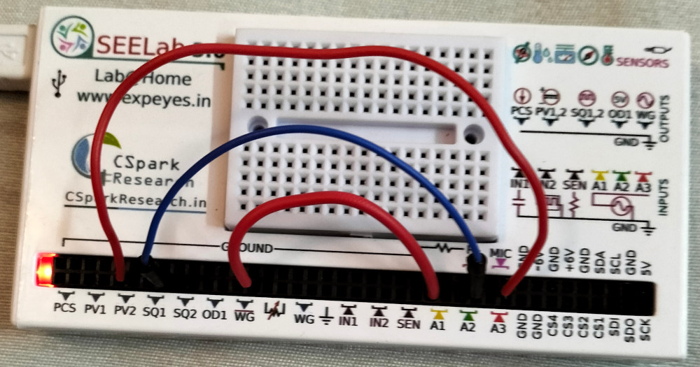
4. Circuit Diagram / Setup
- AC Setup: Connect WG (Waveform Generator) to A1.
- DC Setup: Connect PV2 (Programmable Voltage) to A3.
- Mixed/Blocked Setup: Connect SQ1 (0-5V Square Wave) to one end of a $0.1\text{ }\mu F$ capacitor. Connect the other end of the capacitor to A2.
5. Procedure
- Open the SEELab3 software and select the “AC/DC Difference” or “Oscilloscope” tool.
- Observe DC: Set PV2 to $+3V$. Observe the trace on channel A3. It should be a steady horizontal line. Change PV2 to $-1V$ and notice the line moves below the zero-axis.
- Observe AC: Set WG to a frequency of $50\text{ Hz}$ and an amplitude of $3V$. Observe the trace on channel A1. Adjust the “Timebase” (ms/div) to see multiple cycles.
- Observe SQ1 Blocking: Observe the signal on A2. Note how the $0-5V$ square wave (which is DC-offset) becomes centered around $0V$ after passing through the capacitor.
- Compare the traces simultaneously on the screen to visualize the differences in stability and polarity.
6. Observation Table
| Source | Set Value | Waveform Shape | Polarity Change? |
|---|---|---|---|
| PV2 (DC) | $+3V$ | ||
| PV2 (DC) | $-1V$ | ||
| WG (AC) | $50\text{ Hz}, 3V$ | ||
| SQ1 (Filtered) | $100\text{ Hz}$ |
7. Error Analysis
The primary sources of error in visualizing these waveforms include:
- Quantization Error: The resolution of the Analog-to-Digital Converter (ADC) can cause small “steps” in the DC line if the vertical scale is too large.
- Offset Error: Small calibration offsets in the SEELab inputs may show $0V$ slightly above or below the actual axis.
- Capacitor Leakage: For very low-frequency AC, the $0.1\text{ }\mu F$ capacitor may not block DC perfectly if it has high internal leakage.
8. Results and Discussion
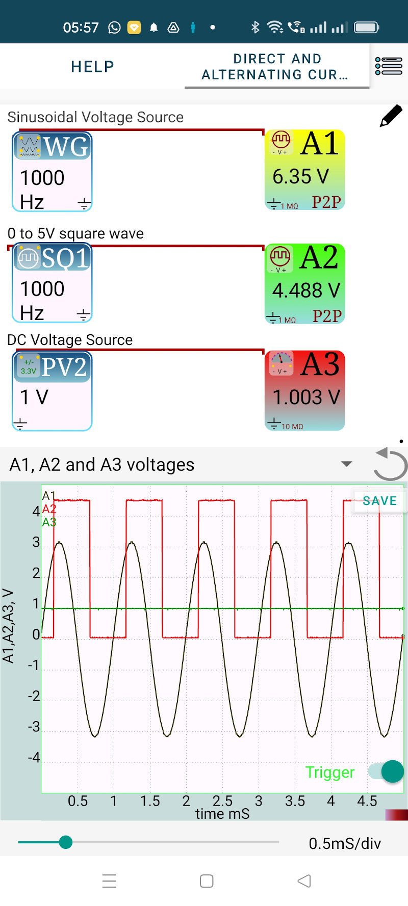
- The DC signal appears as a straight line, indicating the voltage is constant over time.
- The AC signal appears as a sine wave, indicating that the voltage changes magnitude and direction periodically.
- The capacitor effectively blocked the DC component of the SQ1 signal, shifting the waveform to be symmetrical around the zero-axis.
9. Troubleshooting
| Symptom | Possible Cause | Corrective Action |
|---|---|---|
| DC line is not straight | High electrical noise. | Check connections; run laptop on battery. |
| AC wave is blurry | Timebase is too slow. | Adjust the “ms/div” slider to a smaller value. |
| No signal on A3 | Channel not enabled. | Ensure the checkbox for A3 is ticked in the UI. |
10. Viva-Voce Questions
Q1. What is the frequency of a steady DC signal?
Ans: The frequency of a steady DC signal is $0\text{ Hz}$, as it does not repeat or alternate over time.
Q2. Why is AC used for long-distance power transmission instead of DC?
Ans: AC voltage can be easily stepped up or down using transformers. Stepping up to high voltage reduces current, which minimizes energy loss ($I^2R$ loss) in transmission lines over long distances.
Q3. How does a capacitor "block" DC?
Ans: When DC is applied, the capacitor charges up to the source voltage and then stops the flow of current. In AC, the capacitor constantly charges and discharges as the polarity flips, effectively allowing the "signal" to pass through. In the case of SQ1 which alternates from 0V to 5V, the average value of 2.5V is blocked by the capacitor, giving you a signal oscillating between -2.5 to 2.5 V