Experiment: Phase and Amplitude in AC Resistive Circuits
1. Aim
To explore the relationship between voltage and current in an AC circuit containing only resistors, and to verify that they are in phase.
2. Apparatus / Components Required
- SEELab3 or ExpEYES-17 unit
- Two resistors ($R_1 = 1000\text{ }\Omega$ and $R_2 = 560\text{ }\Omega$ or similar)
- Connecting wires
- PC or Smartphone with SEELab3 software
3. Theory & Principle
In a purely resistive AC circuit, the current ($I$) at any instant is directly proportional to the instantaneous voltage ($V$) across the resistor, according to Ohm’s Law: \(I(t) = \frac{V(t)}{R}\)
If the applied voltage is sinusoidal, $V(t) = V_p \sin(\omega t)$, then the current is: \(I(t) = \frac{V_p}{R} \sin(\omega t)\)
This shows that in a resistor, the voltage and current waveforms reach their peaks and zero-crossings at the exact same time. We say that the voltage and current are in phase, meaning the phase difference ($\phi$) is $0^\circ$.
Current Measurement Method: Since SEELab3 measures voltage, we measure the current indirectly. By placing a known resistor ($R_1$) in series, the voltage measured across it ($V_{R1}$) is a direct representation of the current flowing through the circuit ($I = V_{R1} / R_1$).
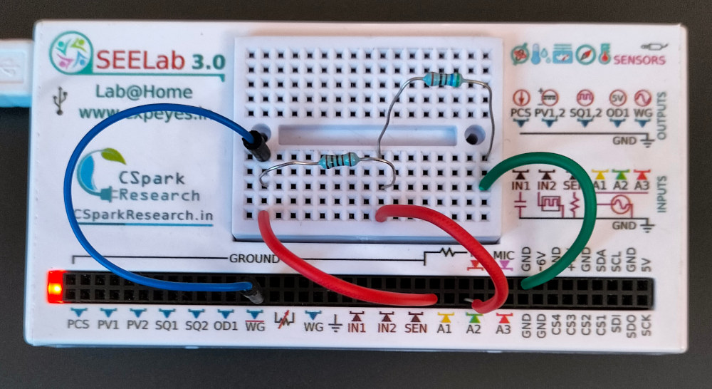
4. Circuit Diagram / Setup
- Connect $R_2$ and $R_1$ in series between WG (Waveform Generator) and GND.
- Connect A1 to WG (to measure the total applied voltage).
- Connect A2 to the junction between $R_1$ and $R_2$ (to measure the voltage across $R_1$, which represents the current).
- The voltage across $R_2$ is calculated by the software as $V_{A1} - V_{A2}$.
5. Procedure
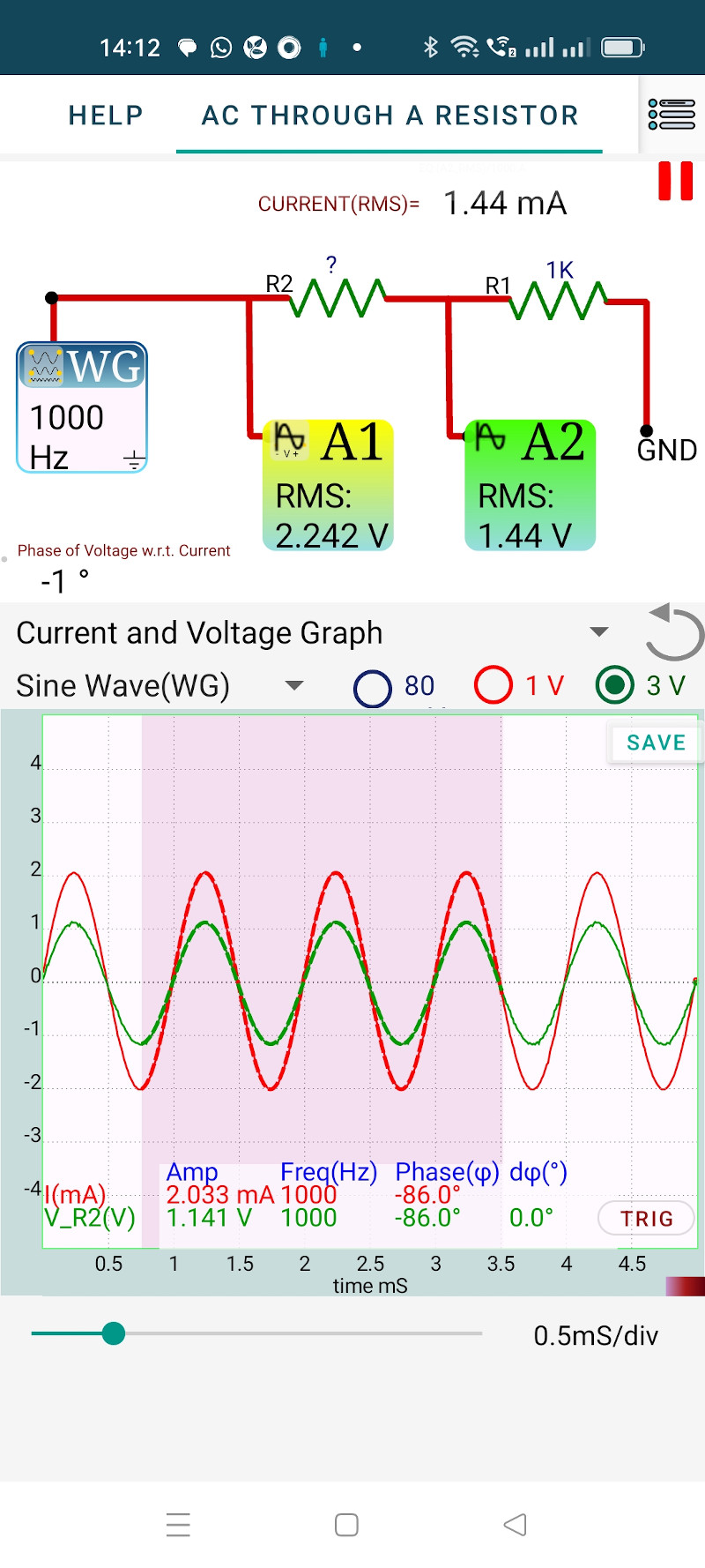
- Open the SEELab3 app and select the “AC through Resistor” experiment.
- Observe the two sine waves on the screen. Note that they cross the zero-axis and reach their maxima simultaneously.
- Use the “Measure” or “Analyze” tool to obtain the peak voltages ($V_p$) and phase difference ($\phi$). You can tap on the A1 or A2 icons in the app to select the parameter to be viewed.
- Calculate the RMS values: $V_{RMS} = V_p / \sqrt{2}$.
6. Observation Table
Reference Resistor ($R_1$): ____ $\Omega$
| Parameter | Measured Value |
|---|---|
| Peak Voltage across $R_2$ ($V_{p2}$) | |
| Peak Voltage across $R_1$ ($V_{p1}$) | |
| Calculated Peak Current ($I_p = V_{p1}/R_1$) | |
| Phase Difference ($\phi$) | |
| Calculated Resistance ($R_2 = V_{p2}/I_p$) |
7. Error Analysis
- Input Loading: The $1\text{ M}\Omega$ input impedance of A2 is in parallel with $R_1$. For a $1\text{ k}\Omega$ resistor, this introduces an error of only $0.1\%$.
- Tolerance: Most standard resistors have a $\pm 5\%$ tolerance. Measure the resistors with the SEELab ohmmeter first to improve the accuracy of your $R_2$ calculation.
- Thermal Noise: At very low signal amplitudes, electronic noise may make the zero-crossing point appear to jitter, leading to small errors in the measured phase angle.
8. Results and Discussion
- The voltage and current waveforms are in phase, as they reach their peaks at the same time.
- The calculated value of $R_2$ is ____ $\Omega$, which matches the labeled value within experimental error.
- For a purely resistive load, the phase angle $\phi$ is approximately 0 degrees.
9. Precautions
- Impedance: Ensure the resistors used are much smaller than the $1\text{ M}\Omega$ input impedance of the SEELab terminals.
- Connections: Ensure the series junction is tight to avoid noisy readings at A2.
- Frequency: Avoid extremely high frequencies where stray capacitance of the breadboard might begin to affect the phase.
10. Troubleshooting
| Symptom | Possible Cause | Corrective Action |
|---|---|---|
| Waves are shifted | Reactive component used. | Verify that you are not accidentally using an inductor or capacitor. |
| A2 signal is zero | Broken junction. | Check the connection between $R_1$, $R_2$, and A2. |
| RMS values look wrong | Clipping signal. | Reduce the WG amplitude so the peaks are within the $\pm 16V$ range. |
11. Viva-Voce Questions
Q1. What does it mean when we say two waveforms are "in phase"?
Ans: It means both waveforms reach their maximum, minimum, and zero values at the same instant of time. The phase angle ($\phi$) between them is zero.
Q2. Does the resistance of a resistor change with the frequency of the AC signal?
Ans: For an ideal resistor, the resistance is independent of frequency. However, at extremely high frequencies (MHz range), "skin effect" and stray inductance can cause the effective resistance to change.
Q3. How is the peak voltage ($V_p$) related to the RMS voltage ($V_{RMS}$)?
Ans: For a sinusoidal wave, $V_{RMS} = \frac{V_p}{\sqrt{2}} \approx 0.707 \cdot V_p$.
Q4. Why is the voltage across R1 used to represent the current?
Ans: According to Ohm's Law ($V = IR$), the voltage across a resistor is directly proportional to the current. Since $R_1$ is constant, the shape and phase of the voltage waveform across it are identical to the current waveform.
Q5. What is the power factor of a purely resistive circuit?
Ans: The power factor is $\cos(\phi)$. Since $\phi = 0^\circ$ for a resistor, $\cos(0^\circ) = 1$. This is called a **unity power factor**.