Experiment: Phase and Resonance in Series RLC Circuits
1. Aim
To study the phase relationships between voltage and current in a series RLC circuit and to observe the phenomenon of series resonance using a Capacitor-Inductor-Resistor (C-L-R) configuration.
2. Apparatus / Components Required
- SEELab3 or ExpEYES-17 unit
- One Resistor ($R = 1000\text{ }\Omega$)
- One Inductor ($L \approx 10\text{ mH}$ to $100\text{ mH}$, typical winding resistance $\approx 20\text{ }\Omega$)
- One Capacitor ($C \approx 0.1\text{ }\mu F$ to $1\text{ }\mu F$)
- Connecting wires
- PC or Smartphone with SEELab3 software
3. Theory & Principle
A series RLC circuit is governed by Kirchhoff’s Voltage Law (KVL), which states that the sum of voltages across the inductor ($L$), resistor ($R$), and capacitor ($C$) must equal the applied source voltage ($v$):
\[L\frac{di}{dt} + iR + \frac{q}{C} = v_m \sin(\omega t)\]The total opposition to the current is the Impedance ($Z$): \(Z = \sqrt{R^2 + (X_L - X_C)^2}\)
Resonance
At the Resonant Frequency ($f_r$), the inductive reactance ($X_L$) and capacitive reactance ($X_C$) cancel each other out ($X_L - X_C = 0$): \(f_r = \frac{1}{2\pi\sqrt{LC}}\)
At resonance, the circuit becomes purely resistive. The voltages across $L$ and $C$ are equal in magnitude but $180^\circ$ out of phase. In this C-L-R sequence, we monitor the intermediate nodes to visualize these individual components.
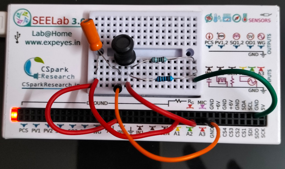
4. Circuit Diagram / Setup
- Series Connection: Connect WG $\rightarrow$ Capacitor ($C$) $\rightarrow$ Inductor ($L$) $\rightarrow$ Resistor ($R$) $\rightarrow$ GND.
- A1 Connection: Connect A1 to WG (measures total voltage $V_{total}$ across the whole string).
- A3 Connection: Connect A3 to the junction (midpoint) between C and L.
- A2 Connection: Connect A2 to the junction (midpoint) between L and R.
Voltage measurements derived by the software:
- $V_C$ (Voltage across Capacitor): Calculated as $A1 - A3$.
- $V_L$ (Voltage across Inductor): Calculated as $A3 - A2$.
- $V_R$ (Voltage across Resistor): Measured directly at A2 (represents current $I$).
- $V_{LC}$ (Combined Reactance): Calculated as $A1 - A2$.
5. Procedure
- Launch the SEELab3 software and select the “AC Through RLC” experiment.
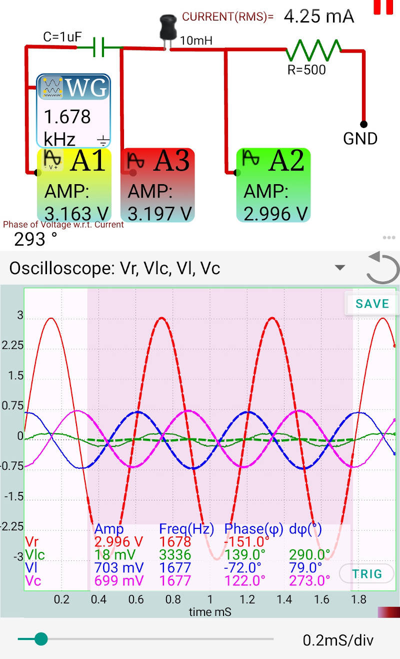
- Set WG to a sine wave. Start near the expected resonance (e.g., $1600\text{ Hz}$).
- Enable traces for A1, A2, and A3.
- Fine-tune the frequency to minimize the voltage across the L-C combination ($V_{A1} - V_{A2}$).
- Observe that at resonance, the current ($V_{A2}$) is at its maximum and is in phase with the input voltage ($V_{A1}$).
6. Observation Table
| $R$: ____ $\Omega$ | $L$: ____ mH | $C$: ____ $\mu F$ |
| Frequency $f$ (Hz) | $V_{A1}$ (Total) | $V_{A2}$ ($V_R$) | $V_{A1}-V_{A3}$ ($V_C$) | $V_{A3}-V_{A2}$ ($V_L$) |
|---|---|---|---|---|
| $f_r$ (Resonance) |
7. Error Analysis
- Inductor Resistance: The voltage $V_{A3}-V_{A2}$ at resonance will not be purely reactive due to the $20\text{ }\Omega$ internal resistance. This causes a small residual voltage that is in phase with the current.
- Phase Extraction: Error in $\phi$ increases if the signal-to-noise ratio is low. Ensure the WG amplitude is at least $3\text{ V}$.
- Stray Capacitance: At very high frequencies, the breadboard or wires may introduce stray capacitance, shifting the observed $f_r$ slightly.
8. Results and Discussion
- At $f < f_r$, the voltage across the capacitor ($A1-A3$) is larger than the voltage across the inductor.
- At $f > f_r$, the voltage across the inductor ($A3-A2$) dominates.
- At resonance, $V_C$ and $V_L$ are nearly equal, and their vector sum is minimized.
Sample Data (500 Hz vs 3000 Hz)
At 500 Hz (below resonance), the circuit is capacitive. At 3000 Hz (above resonance), it is inductive.
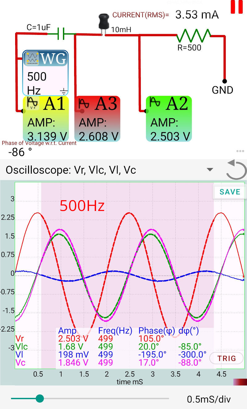
Fig A: 500 Hz (Capacitive)
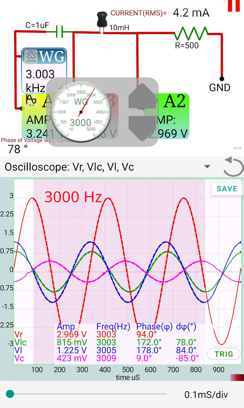
Fig B: 3000 Hz (Inductive)
9. Python Programming & Data
10. Troubleshooting
| Symptom | Possible Cause | Corrective Action |
|---|---|---|
| A3 signal is noisy | Poor contact between C and L. | Check the series junction. |
| Phase looks inverted | Probes A1 and A2 swapped. | Verify A1 is at WG and A2 is at the Resistor. |
11. Viva-Voce Questions
Q1. In this C-L-R setup, how do we find the voltage across the Inductor?
Ans: The Inductor is between A3 and A2. Therefore, $V_L = V_{A3} - V_{A2}$.
Q2. What happens to the total current at resonance?
Ans: The total impedance is at its minimum ($Z=R$), so the current reaches its maximum value.