Experiment: Phase Relationship in AC Capacitive Circuits
1. Aim
To study the phase relationship between voltage and current in an AC circuit containing a capacitor and a resistor, and to verify that current leads voltage in a capacitive circuit.
2. Apparatus / Components Required
- SEELab3 or ExpEYES-17 unit
- One Resistor ($R = 1000\text{ }\Omega$)
- One Capacitor ($C \approx 1\text{ }\mu F$ or similar)
- Connecting wires
- PC or Smartphone with SEELab3 software
3. Theory & Principle
A capacitor opposes changes in voltage by storing energy in an electric field. In a purely capacitive circuit, the current leads the voltage by $90^\circ$ ($\pi/2$ radians). This means the current reaches its peak when the voltage across the capacitor is zero.
The Capacitive Reactance ($X_C$) is given by: \(X_C = \frac{V_C}{I_C} = \frac{1}{2\pi f C}\)
From this, the capacitance can be calculated as: \(C = \frac{I_C}{V_C \cdot 2\pi f}\)
Current Measurement:
We measure the voltage across a series resistor ($R$) to represent the current waveform ($I = V_R / R$). Since $V_{total}$ is measured at A1 and $V_R$ is measured at A2, the voltage across the capacitor is calculated as the difference: $V_C = A1 - A2$. Since both are simultaneously measured, and instantaneous values for both are available as a function of time, direct subtraction is possible.
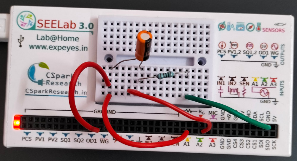
4. Circuit Diagram / Setup
- Connect the Capacitor ($C$) and Resistor ($R$) in series between WG and GND.
- Connect A1 to WG (measures total voltage $V_{total}$).
- Connect A2 to the junction between the Capacitor and the Resistor (measures $V_R$).
- The voltage across the Capacitor is obtained mathematically as $A1 - A2$.
5. Procedure
- Launch the SEELab3 software and select the “AC through Capacitor” experiment.
- Set WG to a sine wave (e.g., $150\text{ Hz}$).
- Enable traces for A1 and A2.
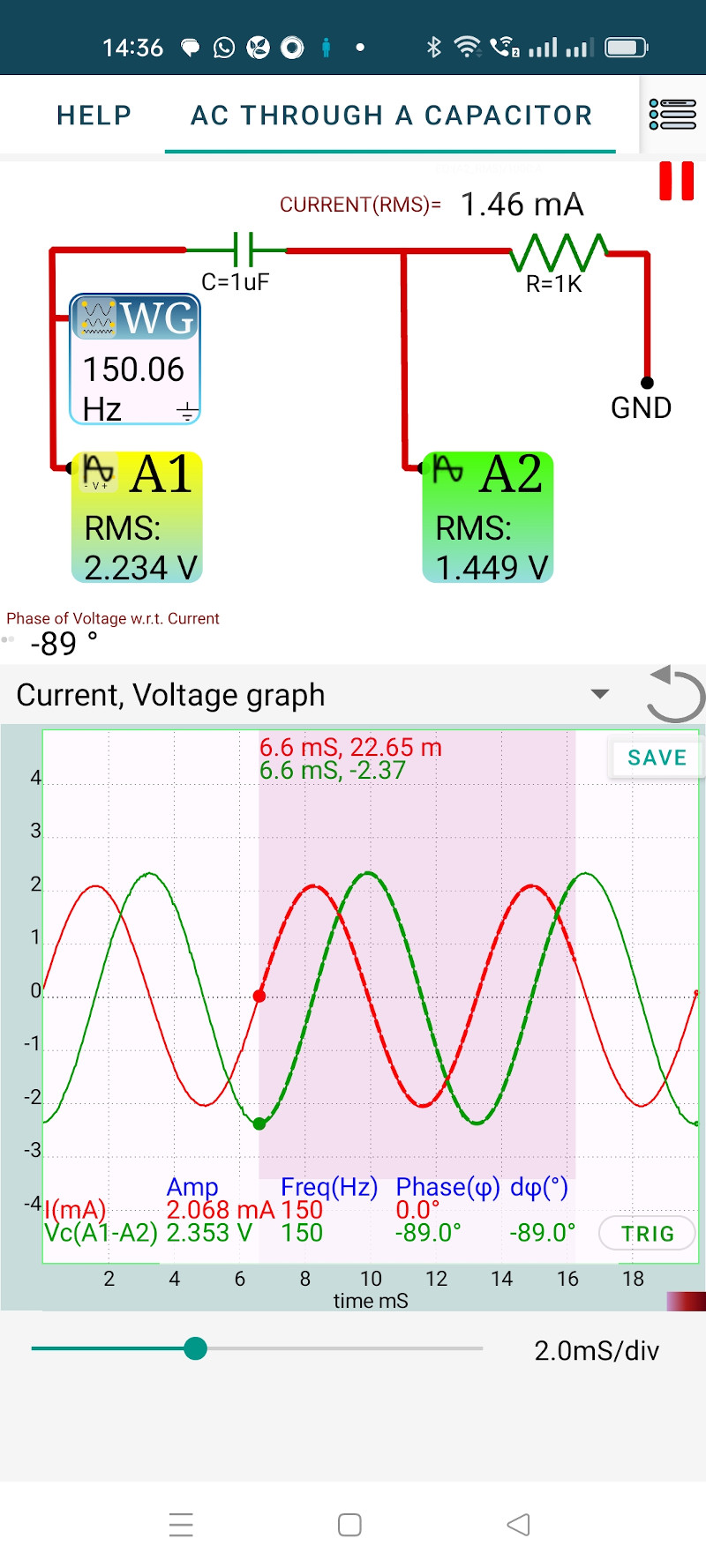
- Select a region of the graph to display calculated values. The software extracts amplitudes and phases by fitting the data to $V = V_0 \sin(\omega t + \theta) + C$.
- Observe that the current (A2) is at its peak when the voltage across the capacitor ($A1-A2$) is at zero, confirming the $90^\circ$ phase shift.
- Compare the calculated $C$ with the value obtained by measuring the capacitor directly using the IN1 terminal.
6. Observation Table
| Parameter | Example Value | Value |
|---|---|---|
| Peak Voltage across Capacitor ($V_C = A1 - A2$) | 2.353 V | |
| Current through Circuit ($I_C = V_{A2}/R$) | 2.068 mA | |
| Frequency ($f$) | 150.06 Hz | |
| Calculated Capacitance ($C$) | 932.5 $\mu F$ | |
| Measured Capacitance (via IN1) | 937 $\mu F$ |
7. Error Analysis
The measurement of capacitance is influenced by the precision of the series resistor $R$ and the sampling resolution of the device.
The percentage error in $C$ can be estimated by: \(\frac{\Delta C}{C} \approx \frac{\Delta I_C}{I_C} + \frac{\Delta V_C}{V_C} + \frac{\Delta f}{f}\)
Key Factors Affecting Accuracy:
- ESR (Equivalent Series Resistance): Real capacitors have a small internal resistance. For large electrolytic capacitors, this ESR can shift the phase slightly away from the ideal $90^\circ$.
- Input Impedance: The $1\text{ M}\Omega$ input impedance of A2 is in parallel with the resistor $R$. Using a $1\text{ k}\Omega$ resistor keeps this error at $0.1\%$, which is negligible.
- Frequency Effect: If the frequency is too high, stray inductance in the leads might interfere; if too low, the capacitive reactance $X_C$ might become large enough to reduce the signal-to-noise ratio.
8. Results and Discussion
- The current waveform reaches its maximum value before the voltage across the capacitor.
- The results confirm the theory within experimental error, as shown by the agreement between calculated and measured capacitance values.
- The phase difference $(\theta_1 - \theta_2)$ extracted from the curve fitting represents the shift between voltage and current.
9. Python Programming & Data
The capture2(samples, gap) function returns voltage vectors which are fitted to determine Amplitudes and Phases. The ratio of Amplitudes gives the Capacitive Reactance.
10. Troubleshooting
| Symptom | Possible Cause | Corrective Action |
|---|---|---|
| No phase shift (0°) | Capacitor is shorted. | Check wiring; ensure A2 is at the junction. |
| Noisy Waveform | Poor GND connection. | Ensure all wires are secure; run laptop on battery. |
| Inaccurate $C$ value | Wrong $R$ value used in calc. | Verify $R$ using the SEELab ohmmeter. |
11. Viva-Voce Questions
Q1. Why does current lead voltage in a capacitor?
Ans: Current is the rate of flow of charge ($I = dq/dt$). Because a capacitor must accumulate charge to develop a voltage ($V = q/C$), the flow of charge (current) must happen first. Therefore, the current reaches its peak before the voltage does.
Q2. What is Capacitive Reactance, and how does it differ from Resistance?
Ans: Capacitive Reactance ($X_C$) is the opposition to AC flow. Unlike resistance, it does not dissipate energy as heat (it stores and releases it) and its value is frequency-dependent ($X_C \propto 1/f$).
Q3. What happens to the phase shift if you add a large resistor in parallel with the capacitor?
Ans: This simulates a "leaky" capacitor. The parallel resistance will allow some current to flow that is in phase with the voltage, reducing the total phase shift to something less than $90^\circ$.