Experiment: Verification of Ohm’s Law Using an AC Source
1. Aim
To verify Ohm’s Law for resistors under an applied AC (sinusoidal) voltage by measuring the peak voltages across two series resistors, calculating the peak current, and confirming that the voltage and current remain in phase for a purely resistive circuit.
2. Apparatus / Components Required
- SEELab3 or ExpEYES-17 unit
- Resistor $R_1 = 1\text{ k}\Omega$
- Resistor $R_2 = 560\text{ }\Omega$
- Connecting wires
- PC or Smartphone with SEELab3 / ExpEYES software
3. Theory & Principle
3.1 Ohm’s Law under AC
Ohm’s Law states that for a linear resistor, the voltage across it is directly proportional to the current through it at every instant:
\[v(t) = i(t) \cdot R\]For a sinusoidal source $v(t) = V_0 \sin(\omega t)$, the instantaneous current is:
\[i(t) = \frac{v(t)}{R} = \frac{V_0}{R}\sin(\omega t) = I_0 \sin(\omega t)\]This shows that for a resistor, voltage and current are always in phase — there is no phase difference between them, regardless of frequency. This is what distinguishes a resistor from a capacitor or inductor.
3.2 Series Resistor Circuit
When two resistors $R_1$ and $R_2$ are connected in series, the same current flows through both (neglecting the $1\text{ M}\Omega$ input impedance of the measurement channels, which is much larger than the circuit resistances). The peak current can therefore be determined from either resistor:
\[I_0 = \frac{V_{R_1,\text{peak}}}{R_1} = \frac{V_{R_2,\text{peak}}}{R_2}\]Rearranging to find the unknown resistance $R_2$:
\[R_2 = \frac{V_{R_2,\text{peak}}}{I_0} = \frac{V_{R_2,\text{peak}} \times R_1}{V_{R_1,\text{peak}}}\]This gives a purely experimental determination of $R_2$ from voltage measurements alone — no separate current meter is required.
3.3 RMS Voltage
For a sinusoidal waveform, the RMS (Root Mean Square) voltage is related to the peak voltage by:
\[V_{rms} = \frac{V_0}{\sqrt{2}} \approx 0.707 \times V_0\]The SEELab3 software computes RMS from instantaneous sampled values over a full cycle:
\[V_{rms} = \sqrt{\frac{1}{N}\sum_{k=1}^{N} v_k^2}\]This general formula works correctly for any waveform shape, not just sinusoids.
3.4 Worked Example
From the experiment on the ExpEYES website:
- Peak voltage across $R_1$: $V_{R_1} = 2.01\text{ V}$
- Peak current: $I_0 = \dfrac{2.01}{1000} = 2.01\text{ mA}$
- Peak voltage across $R_2$: $V_{R_2} = 1.13\text{ V}$
- Calculated $R_2 = \dfrac{1.13}{2.01 \times 10^{-3}} = 562\text{ }\Omega$
This agrees with the marked value of $560\text{ }\Omega$ within experimental tolerance — verifying Ohm’s Law under AC.
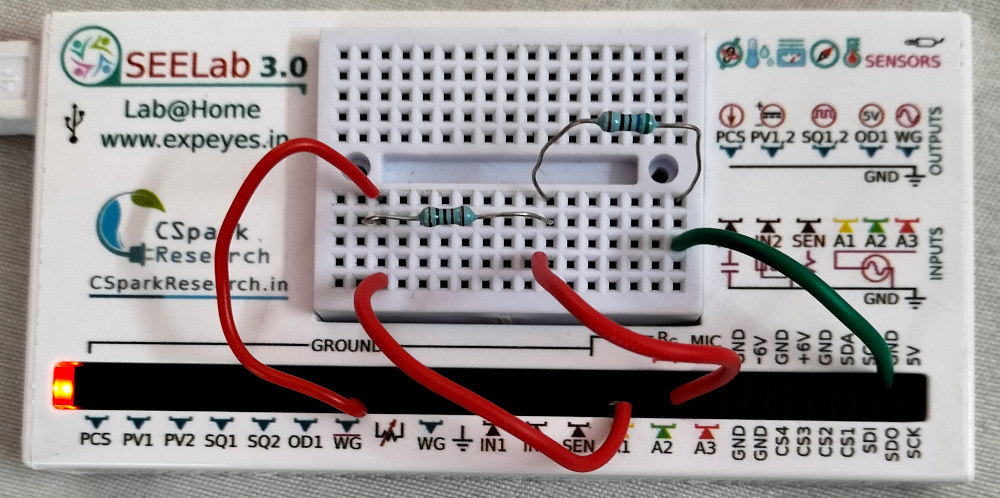
4. Circuit Diagram / Setup
- Connect $R_1$ ($1\text{ k}\Omega$) and $R_2$ ($560\text{ }\Omega$) in series.
- Connect the free end of $R_1$ to WG (the AC sinusoidal source).
- Connect the free end of $R_2$ to GND.
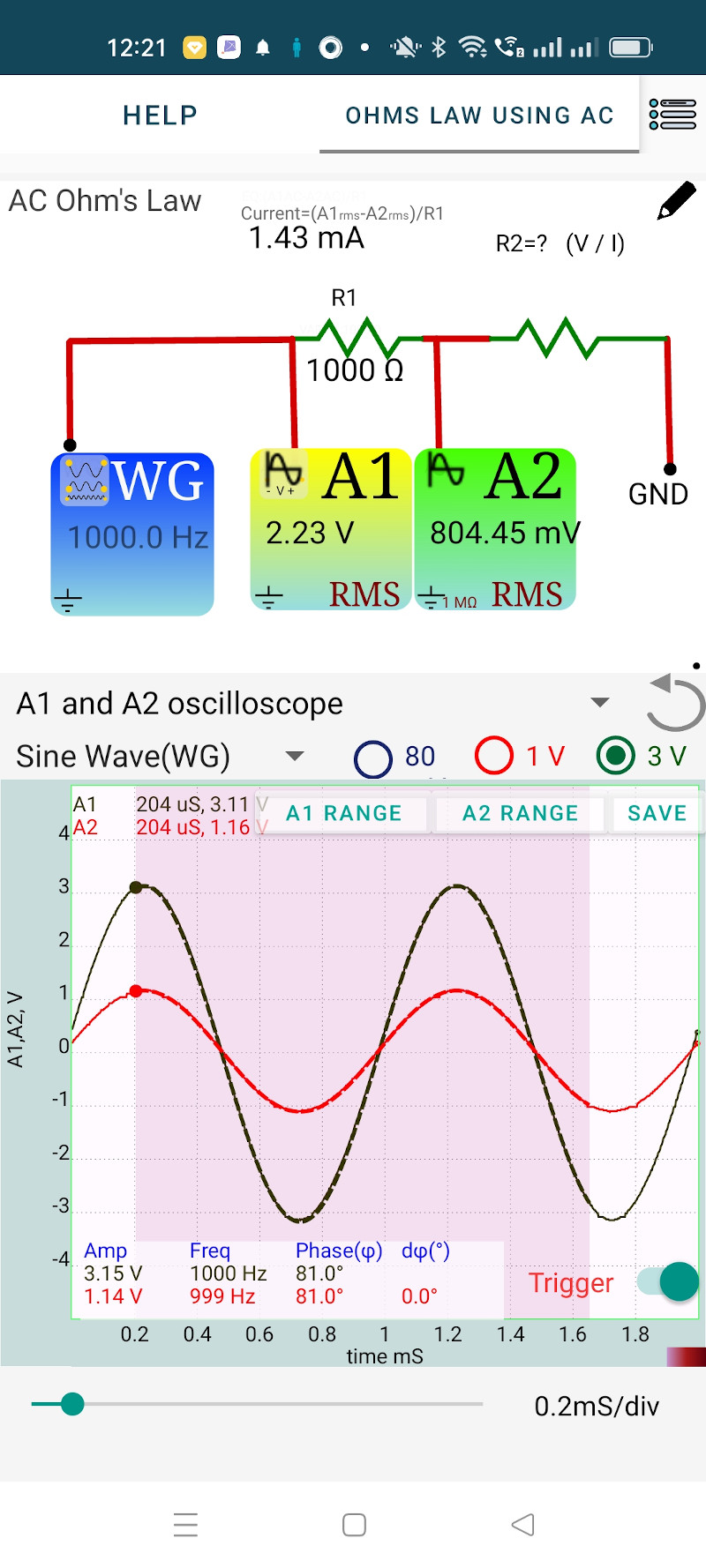
- Connect the WG end (top of $R_1$) to A1 — this monitors the total applied voltage $V_{WG}$.
- Connect the junction between $R_1$ and $R_2$ to A2 — this monitors $V_{R_2}$ directly.
- The voltage across $R_1$ is then $V_{R_1} = V_{A1} - V_{A2}$.
5. Procedure
- Open the SEELab3 / ExpEYES app and select the “Ohm’s Law (AC)” experiment.
- Set the WG to a suitable frequency — $500\text{ Hz}$ is a good starting point — with a moderate amplitude.
- Click “Start”. Two traces will appear:
- A1 — the total applied voltage (also the voltage across both $R_1 + R_2$)
- A2 — the voltage across $R_2$
- Select a region of the graph (a clean sinusoidal section). The software will analyse it and display:
- Peak voltage of each trace
- Frequency
- Phase difference between A1 and A2
- Record the peak voltages from the display. Note that the phase difference between A1 and A2 should be $0°$, confirming that both traces are in phase (as expected for a resistive circuit).
- Observe the RMS values displayed on the channel icons. Verify that $V_{rms} \approx V_{peak}/\sqrt{2}$.
- Calculate $I_0$ from $V_{R_1,\text{peak}} / R_1$ and then compute $R_2 = V_{R_2,\text{peak}} / I_0$.
- Compare the calculated $R_2$ with its marked value.
- Optional: Repeat at different frequencies (e.g., 100 Hz, 1000 Hz, 2000 Hz) to confirm that the result is frequency-independent — a key property of resistors.
Steady State Response (Phone App)
Steady State Setup For ExpEYES17
6. Observation Table
| $R_1$ (marked): ____ $\Omega$ | $R_2$ (marked): ____ $\Omega$ |
6a. Voltage and Phase Measurements
| Frequency $f$ (Hz) | $V_{A1,\text{peak}}$ (V) | $V_{A2,\text{peak}}$ (V) | $V_{R_1} = V_{A1} - V_{A2}$ (V) | Phase diff. $\phi$ (°) |
|---|---|---|---|---|
| 100 | ||||
| 500 | ||||
| 1000 | ||||
| 2000 |
6b. Ohm’s Law Verification (at $f = 500\text{ Hz}$)
| Quantity | Formula | Value |
|---|---|---|
| Peak voltage across $R_1$ | $V_{R_1} = V_{A1} - V_{A2}$ | ____ V |
| Peak current $I_0$ | $I_0 = V_{R_1} / R_1$ | ____ mA |
| Peak voltage across $R_2$ | $V_{R_2} = V_{A2}$ | ____ V |
| Calculated $R_2$ | $R_2 = V_{R_2} / I_0$ | ____ $\Omega$ |
| Marked value of $R_2$ | — | ____ $\Omega$ |
| Percentage error | $\dfrac{\left\lvert R_{2,\text{calc}} - R_{2,\text{marked}} \right\rvert}{R_{2,\text{marked}}} \times 100$ | ____ % |
6c. RMS Verification
| Channel | $V_{\text{peak}}$ (V) | $V_{rms,\text{calc}} = V_{\text{peak}}/\sqrt{2}$ (V) | $V_{rms,\text{displayed}}$ (V) | Match? |
|---|---|---|---|---|
| A1 | ||||
| A2 |
7. Results and Discussion
- The peak voltage across $R_1$ was found to be ____ V, giving a peak current of ____ mA.
- The peak voltage across $R_2$ was ____ V, yielding a calculated resistance of ____ $\Omega$, which agrees with the marked value of $560\text{ }\Omega$ within ____ %.
- The phase difference between the two voltage traces was measured to be ____ °, confirming that voltage and current are in phase for a resistive element under AC, as predicted by Ohm’s Law.
- The RMS voltages displayed by the software agreed with $V_{peak}/\sqrt{2}$ to within experimental error, verifying the sinusoidal nature of the waveform.
- The calculated value of $R_2$ remained consistent across all tested frequencies, confirming that resistance is frequency-independent — a fundamental property that distinguishes resistors from reactive components.
8. Precautions
- Input Impedance Effect: The $1\text{ M}\Omega$ input impedance of channels A1 and A2 is in parallel with the circuit elements they monitor. For the resistor values used here ($R_1 = 1\text{ k}\Omega$, $R_2 = 560\text{ }\Omega$), this loading effect is negligible (less than $0.1\%$). For very high circuit resistances (e.g., $> 100\text{ k}\Omega$), this error becomes significant and must be corrected.
- Clean Region Selection: When the software analyses the selected region of the graph to extract peak voltage and phase, select a portion with at least 2–3 complete, undistorted sinusoidal cycles. Avoid the transient start-up region.
- Resistor Tolerance: Standard resistors have $\pm 5\%$ tolerance (gold band) or $\pm 1\%$ (brown band). A discrepancy of a few percent between the calculated and marked value is expected and acceptable.
- Stable Amplitude: Ensure the WG amplitude is set such that the peak voltage does not saturate the input channels. Keep $V_{A1,\text{peak}} < 3.3\text{ V}$ for safe operation.
9. Troubleshooting
| Symptom | Possible Cause | Corrective Action |
|---|---|---|
| Both traces are identical / overlapping | A1 and A2 are connected to the same node. | Check that A2 is at the junction between $R_1$ and $R_2$, not at the WG terminal. |
| Phase difference is not $0°$ | A reactive component (capacitor, inductor) is unintentionally in the circuit, or the connections are wrong. | Inspect the breadboard; ensure only resistors are in the signal path. |
| Calculated $R_2$ is far from $560\text{ }\Omega$ | Resistors are swapped ($R_1$ and $R_2$ interchanged) or wrong components used. | Measure both resistors independently with a multimeter before connecting. |
| Waveforms are noisy or irregular | Loose breadboard connections. | Re-seat all component leads; ensure firm contact in the breadboard. |
10. Viva-Voce Questions
Q1. Does Ohm's Law hold for AC? Is there any difference from the DC case?
Ans: Yes, Ohm's Law holds instantaneously for a resistor under AC: $v(t) = i(t) \cdot R$ at every instant. The difference from DC is that both $v$ and $i$ are time-varying sinusoids, but their ratio at every moment remains the constant $R$. The law also holds for RMS values: $V_{rms} = I_{rms} \cdot R$. The key point is that there is no phase shift between voltage and current for a pure resistor, unlike for capacitors or inductors.
Q2. Why is it valid to determine the current through $R_2$ by measuring the voltage across $R_1$?
Ans: Because $R_1$ and $R_2$ are in series, the same current flows through both at every instant (Kirchhoff's Current Law). Measuring the voltage across the known resistor $R_1$ and dividing by $R_1$ gives the current $I_0 = V_{R_1}/R_1$. Since this current also flows through $R_2$, we can compute $R_2 = V_{R_2}/I_0$ without inserting an ammeter into the circuit.
Q3. What is RMS voltage, and why is it used instead of peak voltage in AC circuits?
Ans: RMS (Root Mean Square) voltage is the equivalent DC voltage that would deliver the same average power to a resistive load. For a sinusoid: $V_{rms} = V_0/\sqrt{2}$. It is used because power dissipation in a resistor depends on $V^2$: $P = V_{rms}^2/R$. Household supply ratings (e.g., $230\text{ V}$ AC) are always given as RMS values. Peak voltage ($V_0 = 230\sqrt{2} \approx 325\text{ V}$) is relevant only for insulation ratings, not power calculations.
Q4. What would change in this experiment if a capacitor replaced $R_2$?
Ans: Two things would change. First, the voltage across the capacitor would lag behind the current (and hence behind $V_{R_1}$) by $90°$ — the phase difference between A1 and A2 would no longer be $0°$. Second, the impedance of the capacitor $Z_C = 1/(2\pi fC)$ would vary with frequency, so the "calculated resistance" would change at every frequency instead of remaining constant — revealing frequency-dependent behavior characteristic of a reactive element.
Q5. The $1\text{ M}\Omega$ input impedance of the measurement channel is in parallel with $R_2$. At what value of $R_2$ would this loading introduce a $1\%$ error?
Ans: The parallel combination of $R_2$ and $Z_{in} = 1\text{ M}\Omega$ gives an effective resistance $R_{eff} = R_2 \cdot Z_{in}/(R_2 + Z_{in})$. For a $1\%$ error, $R_{eff} = 0.99 \cdot R_2$, which requires $Z_{in}/(R_2 + Z_{in}) = 0.99$, giving $R_2 = Z_{in}/99 \approx 10\text{ k}\Omega$. So for $R_2$ values above approximately $10\text{ k}\Omega$, the input impedance of the channel begins to introduce more than $1\%$ loading error and must be accounted for.