Experiment: Principles of an AC Generator
1. Aim
To demonstrate the conversion of mechanical energy into electrical energy and to study the characteristics of the Alternating Current (AC) produced by a rotating magnetic field.
2. Apparatus / Components Required
- SEELab3 or ExpEYES-17 unit
- Solenoid coil (3000 turns)
- Strong Neodymium magnet (Cuboidal or Cylindrical)
- A motor or manual spinning mechanism (to rotate the magnet)
- Connecting wires
- PC or Smartphone with SEELab3 software
3. Theory & Principle
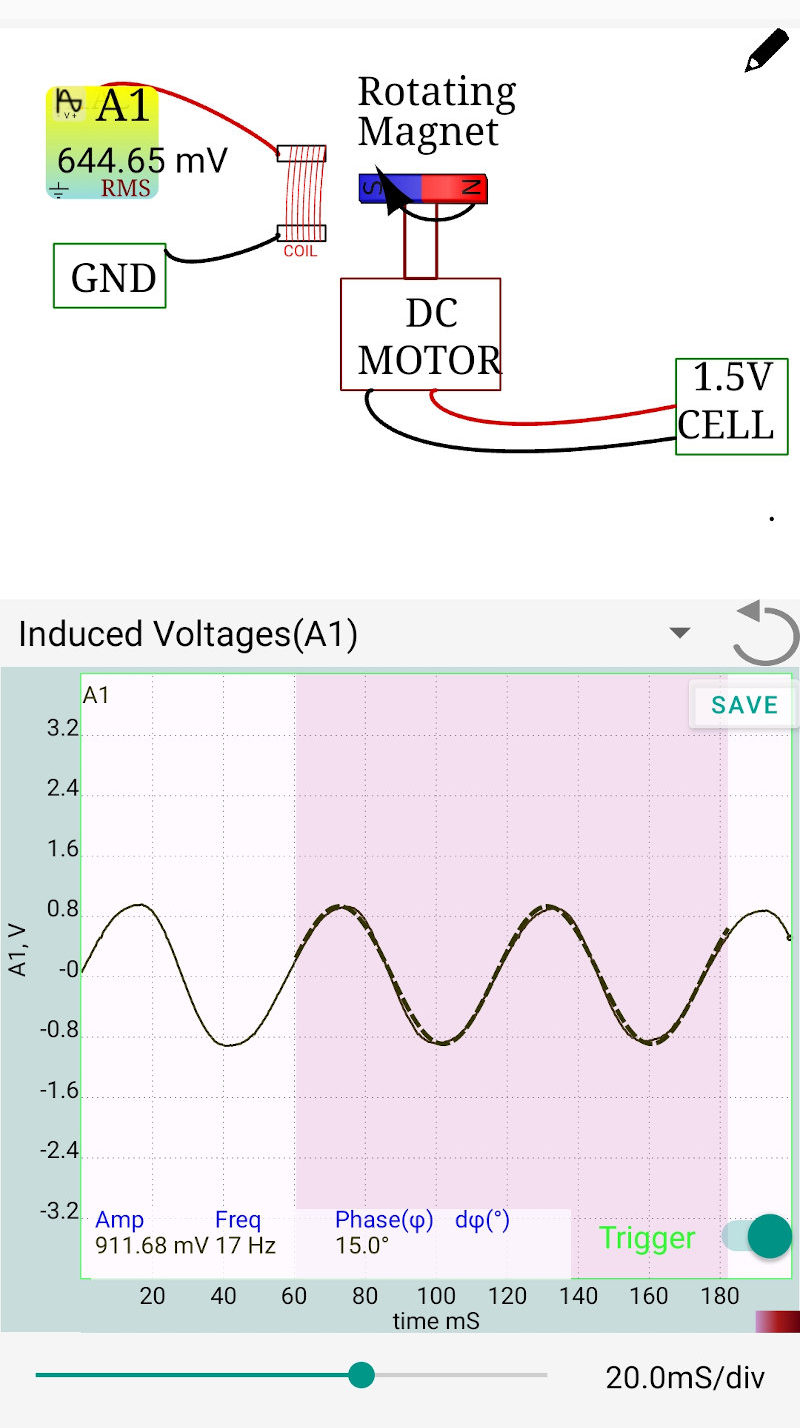
An AC Generator works on the principle of Faraday’s Law of Electromagnetic Induction. When a magnet rotates near a stationary coil, the magnetic flux ($\Phi_B$) passing through the coil changes continuously. This change in flux induces an Electromotive Force (EMF) in the coil.
The induced EMF ($\varepsilon$) follows a sine wave pattern because the rate of change of flux varies sinusoidally with the angle of rotation ($\theta$): \(\varepsilon(t) = \varepsilon_0 \sin(\omega t)\)
Where:
- $\varepsilon_0$ is the peak voltage.
- $\omega$ is the angular frequency ($2\pi f$).
- $t$ is the time.
The peak voltage $\varepsilon_0$ depends on the number of turns in the coil, the strength of the magnet, and the speed of rotation. Faster rotation leads to a higher frequency and a higher peak voltage.
4. Circuit Diagram / Setup
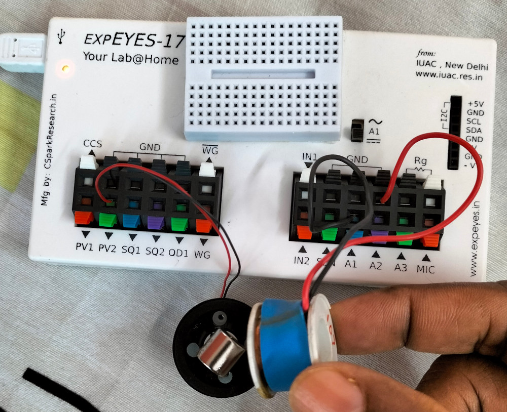
- Coil Connection: Connect the two terminals of the solenoid coil to A1 and GND.
- Magnet Orientation: * Cuboidal Magnet: The poles are on the long faces. Attach it vertically to the motor’s pulley.
- Cylindrical Magnet: Lay it flat so the poles rotate past the coil face.
- Position the magnet such that it can rotate freely very close to one face of the coil.
- If using a DC motor, connect it to a separate power source or PV1 (ensure current < 30mA).
5. Procedure
- Open the SEELab3 software and select the “AC Generator” or “Oscilloscope” tool.
- Set the software to display the signal from A1.
- Start rotating the magnet at a constant speed.
- Observe the induced AC waveform on the screen.
- Effect of Speed: Increase the speed of rotation and observe how both the amplitude (height) and frequency (closeness of peaks) of the sine wave change.
- Distance: Move the coil further away from the rotating magnet and observe the drop in induced voltage.
6. Observation Table
| Rotation Speed (Slow/Medium/Fast) | Peak Voltage $V_p$ (V) | Frequency $f$ (Hz) |
|---|---|---|
| Slow | ||
| Medium | ||
| Fast |
7. Error Analysis
- Magnetic Alignment: If the axis of rotation is not perfectly aligned with the center of the coil, the sine wave may appear distorted or asymmetrical.
- Mechanical Loading: The “Cogging” effect (magnetic attraction between the magnet and the coil’s core, if any) can cause non-uniform rotation speeds at low RPM.
- Ambient Noise: Long unshielded wires between the coil and SEELab can pick up $50\text{ Hz}$ mains hum, which overlays on the generator signal.
8. Results and Discussion
- The rotating magnet induces an alternating voltage in the coil, as evidenced by the sinusoidal waveform.
- As the speed of rotation increases, the peak voltage increases linearly with frequency ($V_p \propto f$).
- This experiment confirms that mechanical energy is converted into electrical energy.
9. Precautions
- Mechanical Stability: Ensure the rotating magnet is securely balanced to prevent vibrations.
- Proximity: Keep the coil as close to the magnet as possible without physical contact to maximize the induced EMF.
- Input Limits: Do not use high-power industrial generators with the A1 input.
10. Troubleshooting
| Symptom | Possible Cause | Corrective Action |
|---|---|---|
| No waveform on A1 | Coil not connected. | Check wire continuity and GND/A1 links. |
| Signal is very weak | Magnet is too far. | Bring the coil closer to the spinning magnet. |
| Waveform is distorted | Magnet is wobbling. | Re-align the magnet on its axis for smooth rotation. |
11. Viva-Voce Questions
Q1. Is the electricity generated in our homes produced by rotating magnets or rotating coils?
Ans: In large power plants (hydro, thermal, or nuclear), large electromagnets (the rotor) are usually rotated inside stationary coils (the stator). This is safer and more efficient for handling high currents.
Q2. Why does the peak voltage increase when the magnet spins faster?
Ans: According to Faraday's Law, induced EMF is proportional to the rate of change of flux ($d\Phi/dt$). Faster rotation means the magnetic field lines are cut more quickly, increasing the rate of change and thus the voltage.
Q3. What part of the generator is the "Stator" and what is the "Rotor" in this setup?
Ans: The stationary coil is the Stator, and the rotating magnet (or the assembly it is attached to) is the Rotor.
Q4. How can you increase the maximum power output of this generator?
Ans: Power can be increased by using a stronger magnet, increasing the number of turns in the coil ($N$), using a soft iron core to concentrate flux, or increasing the rotational speed.
3 Phase AC Generator
A 3D Printable 3 Phase AC Generator Demo