Experiment: Separating AC and DC Components
1. Aim
To demonstrate how a composite signal (containing both AC and DC) can be separated into its individual components using a capacitor and a resistor.
2. Apparatus / Components Required
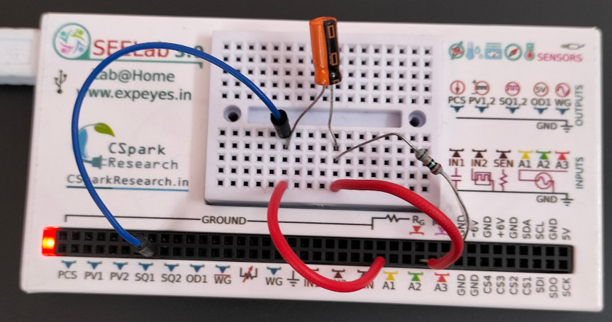
- SEELab3 or ExpEYES-17 unit
- One Capacitor ($C = 1\text{ }\mu F$ or $0.1\text{ }\mu F$)
- One Resistor ($R = 100\text{ k}\Omega$)
- Connecting wires
- PC or Smartphone with SEELab3 software
3. Theory & Principle
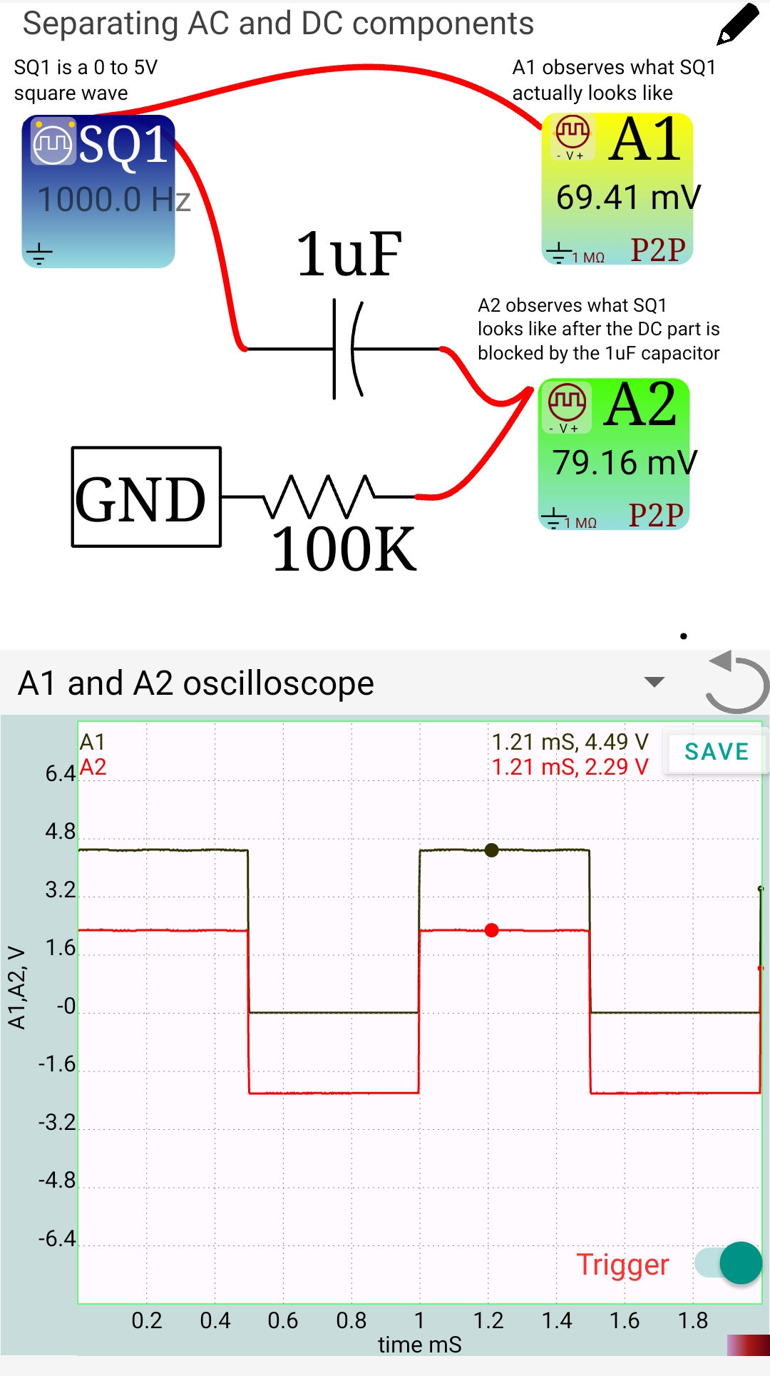
A $0$ to $5V$ square wave (like the one from SQ1) is mathematically a combination of:
- A DC component of $+2.5V$ (the average value).
- An AC component (a square wave oscillating between $-2.5V$ and $+2.5V$).
Capacitive Blocking: A capacitor has a very high reactance ($X_C = 1/2\pi fC$) at low frequencies and acts as an open circuit to DC ($0\text{ Hz}$). However, it allows AC signals to pass through. By placing a capacitor in series with the signal and a resistor to ground, we create a High Pass Filter that “blocks” the steady DC voltage and “passes” only the alternating part.
4. Circuit Diagram / Setup
- Reference Signal: Connect SQ1 directly to A1 to monitor the original $0-5V$ signal.
- AC Separation: Connect SQ1 to one end of the $1\text{ }\mu F$ capacitor.
- Measurement: Connect the other end of the capacitor to A2.
- Load Resistor: Connect a $100\text{ k}\Omega$ resistor from A2 to GND. This provides a reference path for the AC signal.
5. Procedure
- Open the SEELab3 software and select the “AC/DC Separation” or “Oscilloscope” tool.
- Set SQ1 to a frequency of $500\text{ Hz}$.
- Observe the trace on A1. It should be a square wave jumping between $0V$ and $5V$. Note that its average value is $+2.5V$.
- Observe the trace on A2. Note that the signal is now a square wave centered around the zero-axis, oscillating between $-2.5V$ and $+2.5V$.
- Verification: Check the “Mean” or “Average” value displayed for both channels. A1 should show $\approx 2.5V$, while A2 should show $\approx 0V$.
6. Observation Table
| Channel | Signal Source | Min Voltage (V) | Max Voltage (V) | Average (DC) |
|---|---|---|---|---|
| A1 | Direct SQ1 | 0.0 | 5.0 | 2.5 |
| A2 | Via Capacitor | -2.5 | 2.5 | 0.0 |
7. Results and Discussion
- The signal at A1 is a combination of AC and DC because its average value is non-zero.
- The signal at A2 is pure AC because its average value is zero.
- The capacitor successfully blocked the $+2.5V$ DC offset while allowing the $500\text{ Hz}$ frequency component to pass.
- This technique is commonly used in audio amplifiers to pass the sound signal (AC) between stages while blocking the supply voltages (DC).
8. Precautions
- Resistor Importance: Always use the $100\text{ k}\Omega$ resistor to ground at A2. Without it, the capacitor has no discharge path, and the input may “float” or take a long time to stabilize at $0V$.
- Frequency: If the frequency is very low (e.g., $1\text{ Hz}$), the capacitor might start blocking the AC component as well, causing the square wave to “droop” or look like spikes.
- Polarity: If using an electrolytic capacitor, ensure the positive lead is connected to the signal source (SQ1).
9. Troubleshooting
| Symptom | Possible Cause | Corrective Action |
|---|---|---|
| A2 signal is zero | Capacitor is disconnected. | Check the series connection between SQ1, C, and A2. |
| A2 signal still has DC | Resistor missing. | Connect the $100\text{ k}\Omega$ resistor from A2 to GND. |
| Waveform is distorted | Frequency too low. | Increase SQ1 frequency to $100\text{ Hz}$ or higher. |
11. Viva-Voce Questions
Q1. What is meant by the "Average Value" of an AC signal?
Ans: The average value is the DC component of the signal. For a pure AC wave (like a sine wave centered on zero), the positive and negative halves cancel out, resulting in an average of $0V$.
Q2. Why is a capacitor called a "DC Blocking" component?
Ans: Because a capacitor consists of two plates separated by an insulator. DC current cannot flow through the insulator. However, AC can "pass" because the plates constantly charge and discharge, creating a displacement current in the circuit.
Q3. If the SQ1 signal is 0 to 5V, what is its Peak-to-Peak voltage?
Ans: The Peak-to-Peak voltage ($V_{pp}$) is $5.0V$. After removing the DC, the signal becomes $-2.5V$ to $+2.5V$, and the $V_{pp}$ remains $5.0V$.
Q4. What would happen if you used a very small capacitor (e.g., 10pF)?
Ans: A very small capacitor has high reactance even for AC. It would act as a high-pass filter with a very high cutoff frequency, likely blocking the $500\text{ Hz}$ square wave or turning it into sharp spikes (differentiation).
Q5. Where is this principle used in everyday electronics?
Ans: It is used in "AC Coupling" on oscilloscopes, in audio equipment to prevent DC from reaching speakers, and in radio receivers to separate signals from supply voltages.