Radiation Detection and Analysis
| Links:
This was a project I worked on during the summer of 2011 at IUAC, New Delhi, under the guidance of Dr. P Sugathan. Dr. P Sugathan. An ATMEGA32 based MCA was developed at IUAC, and I was entrusted to write firmware for peak detection and segregation, as well as set up an interface and write PC software for displaying the energy spectra. The Python-Tk based GUI I wrote was capable of spectrum analysis, calibration, porting data to XmGrace etc. The device was Calibrated using Co-60
Multi Channel Analyzer
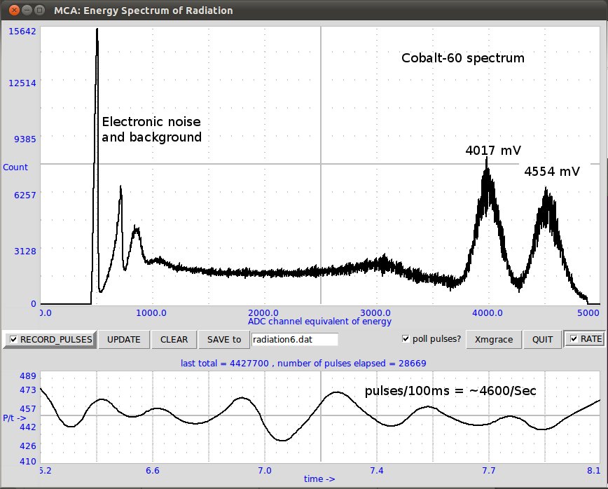
Source used : Cobalt-60 . This is a radioactive isotope of Cobalt with a half life of around 5.17 years . It decays to give Nickel-60 and the activated Nickel nucleus emits two gamma rays of energies 1173 and 1332 KeV.
Detector Used : Sodium Iodide scintillation crystal attached to a photomultiplier tube and a preamplifier included in the unit. [Bicron electronics – IL-496]
The signal was amplified and given to the MCA.
Two peaks at roughly 4017mV and 4554mV were obtained from the Cobalt source. Since these two peaks corresponds to two known gamma energies 1173 keV and 1332 keV respectively, we can calculate the calibration factor as (1332 – 1173) / (4554-4017) = 0.296 keV per channel.
The source was placed around ten cms from the detector and a rate of approximately 4600 pulses/S were observed.
Summary of Multi Channel Analyzers
A multi-channel analyser(MCA) is a standard device used to segregate input voltage pulses based on their amplitude and generate a histogram. An MCA collects & sorts pulses, stores that sorted data and prepares the data for output.
The objective of this project is to design and fabricate a modern MCA with USB computer interface and a Graphical User Interface for spectrum display.
Using an MCA to Plot Energy Spectrum
- Energy of radiations such as alpha particles or gamma rays from standard radioactive sources are measured using radiation detectors coupled to standard pulse processing electronics.
- When radiation is absorbed in detectors, a linear pulse is generated.
- The amplitude of this pulse is proportional to the total energy deposited by the radiation. This pulse is passed through a preamplifier circuit and after proper shaping, it is given as input to the MCA.
- The MCA can now interpret these pulses based on their height and a corresponding energy spectrum can be plotted.
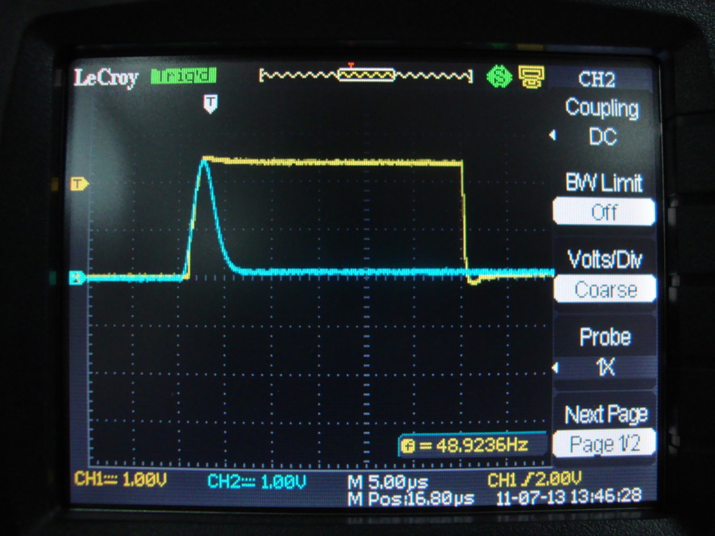
- These pulses typically last a couple of microseconds only .
The MCA is built based on an Atmega32 micro-controller, an Analog to Digital Converter( ADC) and a flash memory for storing the data.
The project involved coding of all software and also performing test runs on the MCA .
Software coded for this purpose:
- Firmware for the atmega32 which interfaces the hardware and receives input
- User end software on the PC which enables basic user controls and plots the data sent over by the hardware
- Additional codes used for troubleshooting etc.
Features of the MCA
- Buffering and stretching of input voltage peak to enable sampling by an ADC.
- 11 bit ADC conversion(2096 channels) using the MCP3208 chip
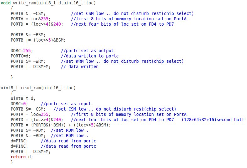
- Reading and writing from an 8K static CMOS memory due to shortage of memory on the ATMEGA32( 2K )
- 38k BAUD serial interface to a PC running the user end software
- User end software has the ability to intermittently poll data stored on the MCA and plot graphs
Implementation
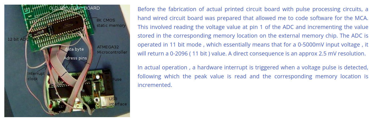
Before the fabrication of actual printed circuit board with pulse processing circuits, a hand wired circuit board was prepared that allowed me to code software for the MCA. This involved reading the voltage value at pin 1 of the ADC and incrementing the value stored in the corresponding memory location on the external memory chip. The ADC is operated in 11 bit mode , which essentially means that for a 0-5000mV input voltage , it will return a 0-2096 ( 11 bit ) value. A direct consequence is an approx 2.5 mV resolution.
In actual operation , a hardware interrupt is triggered when a voltage pulse is detected, following which the peak value is read and the corresponding memory location is incremented.
Example to explain pulse processing
Assume that 1V is present at the input of the ADC. Upon reading this value by the micro-controller , it returns (1000mV/5000mV)*2096 = 419. Following the voltage measurement , the micro-controller reads the 419th memory location , adds 1 to it and writes it back onto that location. In effect , one could plot a histogram by reading the data on memory locations 0-2096 and see a peak at x-axis value 419. Although , the constant presence of 1V on the input will not cause location 419 to be continuously incremented . The software is interrupt driven , and hence , only a pulse with some peak height will cause an increment at the location corresponding to its height.
Since each memory location is only one byte(max value = 255) , 256 pulses on the same channel will cause it to overflow. As a solution to this problem , four bytes(32 bits) each have been allocated to the ADC values . In a nutshell , such a move would mean that 232 pulses with the same height will have to be triggered in order to cause an overflow. And the corresponding radiation overdose , I assume , will not allow any user to witness it !!.
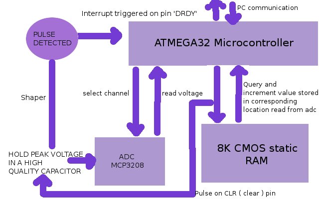
System Diagram
Hardware
MCP3208 ADC
Capable of 12 bit ADC conversion , this IC has 8 input channels and an SPI serial interface for relaying data onto a microcontroller or any other device capable of communicating similarly.
HM62624 EEPROM
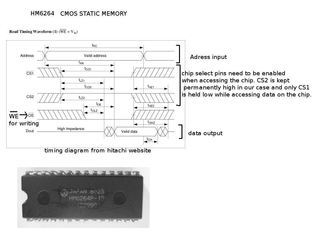
This IC allows for 8 kilobytes of storage locations , each of which can be referenced and modified by means of a 13-bit address code and an 8-bit data buffer.
Testing
Peak stretching circuit for digitizing
The peak voltage of the input pulse is buffered and stored in a capacitor till the ADC finished digitizing the value and a CLEAR pulse is detected.
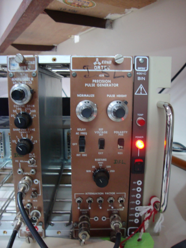
Pulse generator and shaper
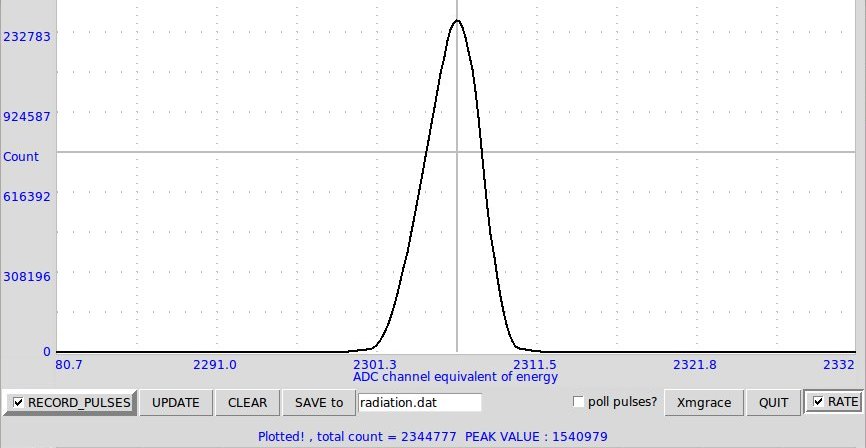
FWHM characterisation : Reliability and precision tests
For approx. 1.5 million pulses from the pulse generator triggered on channel 968 , the peak spread over only three channels. This indicates a precision of around 10 mV for this large a number of pulses from the pulse generator.
Final Board
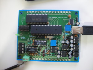 Final board for the Multi Channel Analyzer