Inverting Amplifier using Op-Amp
Inverting Amplifier using Op-Amp
1. Aim
To build an inverting op-amp amplifier using OP07, verify its voltage gain and phase inversion, and study output clipping when input amplitude is increased.
2. Apparatus / Components Required
- SEELab3 unit
- OP07 single-channel op-amp
- Input resistor: $R_i = 1\text{ kOhm}$
- Feedback resistor: $R_f = 10\text{ kOhm}$
- Dual supply for op-amp: approximately $\pm 6\text{ V}$
- Breadboard and connecting wires
- PC/mobile with SEELab3 software
3. Theory & Principle
In an inverting amplifier, the non-inverting terminal is grounded, input is applied to the inverting terminal through $R_i$, and feedback is provided through $R_f$.
For ideal op-amp operation with negative feedback: \[A_v = \frac{V_{out}}{V_{in}} = -\frac{R_f}{R_i}\]
With $R_i = 1\text{ kOhm}$ and $R_f = 10\text{ kOhm}$: \[A_v = -10\]
So the output should be:
- 10 times larger in amplitude than input (within linear region),
- 180 degrees out of phase (inverted).
If input is too large, required output exceeds supply rails and the op-amp saturates, producing clipping.
4. Circuit Diagram / Setup
- Power OP07 with dual rails (about $+6\text{ V}$ and $-6\text{ V}$).
- Connect non-inverting input (+) to GND.
- Connect $R_i = 1\text{ kOhm}$ from WG output to inverting input (-).
- Connect $R_f = 10\text{ kOhm}$ from op-amp output back to inverting input (-).
- Measure:
- input waveform at WG (or input node),
- output waveform at op-amp output.
- Set WG amplitude to around 80 mV initially.
5. Procedure
- Build the circuit and verify all power connections before applying input signal.
- Set WG to a sine wave (for example 500 Hz to 1 kHz) with amplitude about 80 mV.
- Observe input and output simultaneously.
- Record:
- input peak-to-peak voltage $V_{in,pp}$,
- output peak-to-peak voltage $V_{out,pp}$,
- phase relation between input and output.
- Compute gain:
- Increase input amplitude gradually (e.g., up to around 1 V) and observe clipping.
- Note the input level at which output first departs from a clean sine wave.

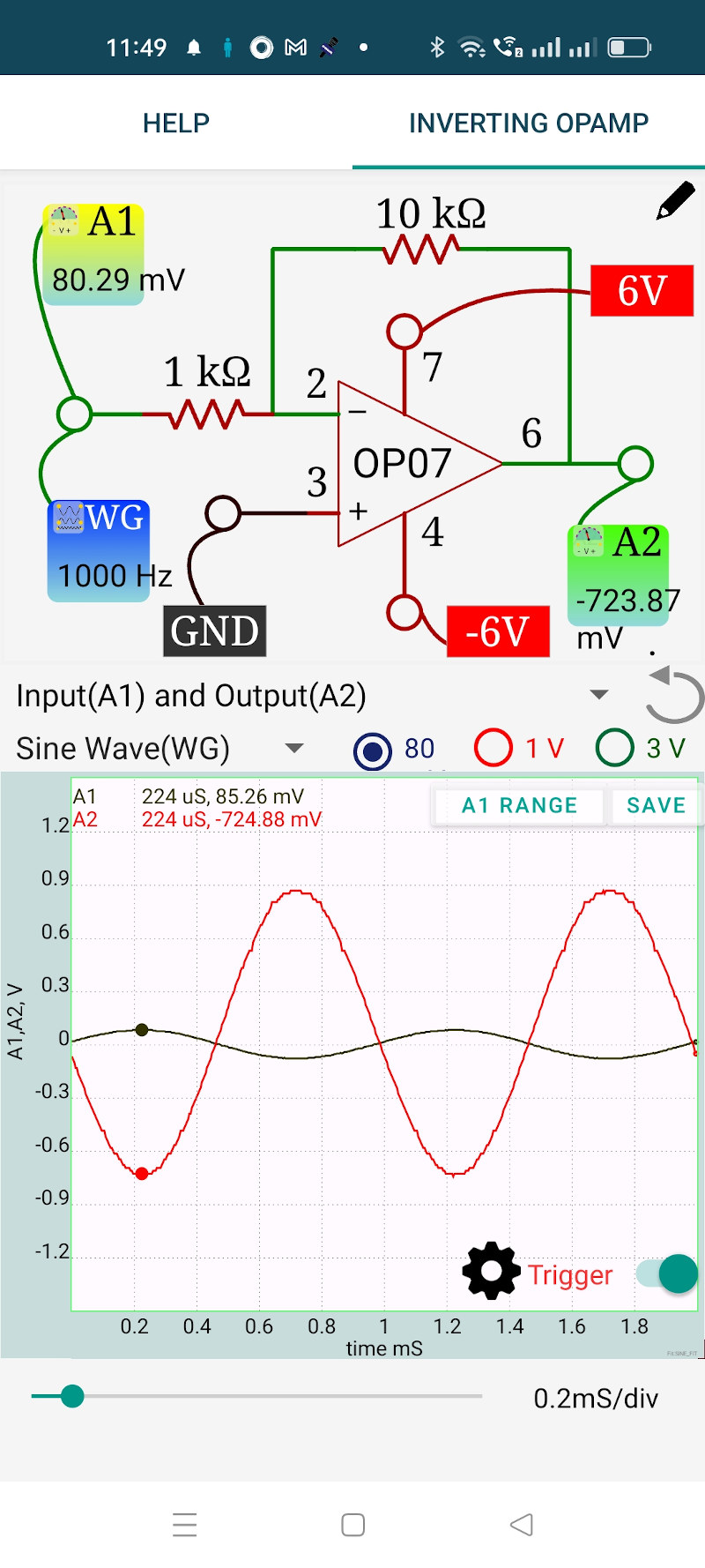
Mobile App
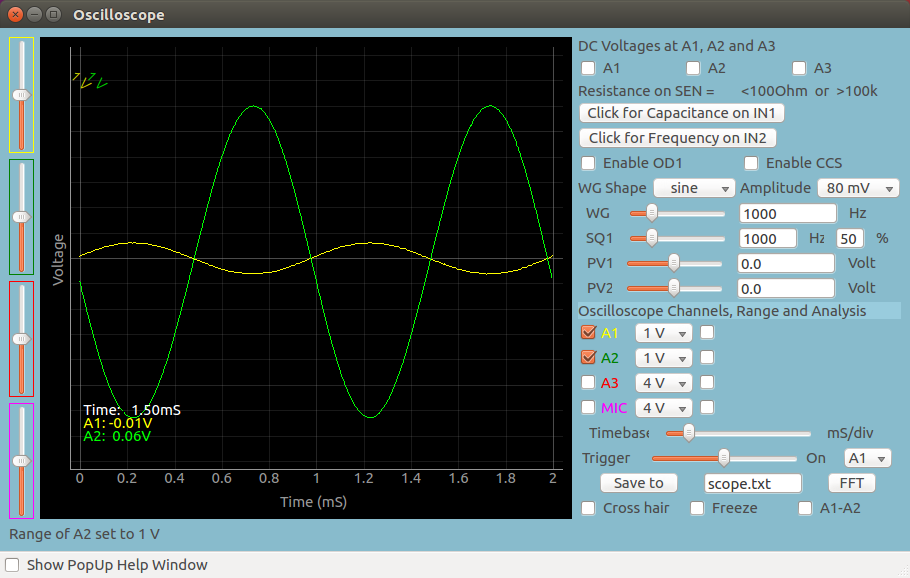
Desktop App
6. Observation Table
| Trial | $V_{in,pp}$ (V) | $V_{out,pp}$ (V) | Calculated Gain $A_v$ | Phase shift | Waveform quality |
|---|---|---|---|---|---|
| 1 (small signal) | |||||
| 2 | |||||
| 3 | |||||
| 4 (high input) |
7. Results and Discussion
- The measured gain in the linear region was approximately ____, close to theoretical value of $-10$.
- Output waveform was inverted relative to input (approximately 180 degrees phase shift).
- At higher input amplitude, output clipped near the op-amp supply limits.
- The clipping confirms that closed-loop gain formula is valid only while the op-amp remains in linear operation.
8. Precautions
- Confirm OP07 pin configuration before wiring.
- Use correct dual supply polarity; wrong polarity can damage the op-amp.
- Start with low input amplitude (around 80 mV) and increase gradually.
- Keep all grounds common between SEELab3 and amplifier circuit.
- Verify resistor values ($R_i$, $R_f$) to avoid incorrect gain.
9. Troubleshooting
| Symptom | Possible Cause | Corrective Action |
|---|---|---|
| No output signal | Missing supply rails or wrong pin connections | Check OP07 power pins and output pin wiring |
| Gain not close to 10 | Wrong resistor values or bad connection at inverting node | Recheck $R_i=1\text{ kOhm}$, $R_f=10\text{ kOhm}$ |
| Output not inverted | Probes connected to wrong nodes | Measure true input node and output node again |
| Severe clipping at low input | Supply rails too low or op-amp wiring error | Verify $\pm 6\text{ V}$ rails and feedback path |
| Noisy/distorted output | Floating ground or loose breadboard contacts | Tighten wiring and ensure common ground |
10. Viva-Voce Questions
Q1. Why is this amplifier called an inverting amplifier?
Ans: Because the output is 180 degrees out of phase with the input. A positive input excursion gives a negative output excursion and vice versa.
Q2. Derive gain for the inverting amplifier.
Ans: With ideal op-amp and negative feedback, input current into op-amp is approximately zero and the inverting node is virtual ground. So current through $R_i$ equals current through $R_f$: $\frac{V_{in}}{R_i} = -\frac{V_{out}}{R_f}$. Therefore, $V_{out}/V_{in} = -R_f/R_i$.
Q3. Why does output clip at high input amplitude?
Ans: The op-amp output cannot exceed its supply rails. If required output from $A_v \cdot V_{in}$ is larger than available swing, the output saturates at rail limits, causing clipping.
Q4. What is a virtual ground in this circuit?
Ans: Due to high open-loop gain and negative feedback, the inverting input is held at nearly 0 V (same as non-inverting grounded input), though it is not directly connected to ground.
Q5. How can gain be increased without changing circuit topology?
Ans: Increase $R_f$ or decrease $R_i$, because $|A_v| = R_f/R_i$. However, larger gain reduces allowable input range before clipping.